Simulasi Pengendalian LED dengan ESP32 dan MicroPython

Simulasi Pengendalian LED dengan ESP32 dan MicroPython

Tutorial ini adalah tutorial pertama dari seri simulator wokwi yang bisa kalian akses di helmydx.my.id. Dalam tutorial ini, kalian tidak membutuhkan perangkat keras ESP32 maupun komponen lainnya. Yang perlu dipersiapkan pada tutorial ini adalah sebuah komputer PC atau laptop yang terkoneksi dengan internet untuk mengakses simulator wokwi.

Baiklah tanpa panjang basa basi, kita masuki tutorial simulasi pengendalian LED dengan ESP32 dan MicroPython.

Langkah pertama, Bukalah browser di laptop kamu misalnya google chrome atau mozilla firefox, lalu buka laman https://wokwi.com/. Selanjutnya kalian akan melihat tampilan laman web seperti gambar dibawah ini. lakukan proses sign up / sign in dengan menggunakan akun google kalian masing-masing.

karena kita akan menggunakan ESP32 sebagai pengendali dan Micropython, maka kita scroll kebawah sampai kita temukan icon Micropython. Selain ESP32, Wokwi juga mendukung beberapa mikrokontroler lain seperti Arduino, STM32 dan Raspberry pi pico.

Setelah kalian klik MicroPython, kalian akan diarahkan ke halaman khusus berisi contoh project dan template simulasi yang menggunakan ESP32. Scroll sedikit kebawah, menuju bagian “Stater Templates”, lalu “NEW PROJECT” pilih jenis ESP32 yang kalian inginkan. Untuk tutorial ini saya akan menggunakan MicroPython on ESP32 sebagai template.

Setelah itu, kita akan melihat halaman simulator ESP32. Simulator ini terdiri dari dua panel utama yaitu panel rangkaian dan panel program. Di sebelah kanan layar kita adalah panel rangkaian, dan di sebelah kiri adalah panel program.

Membuat Rangkaian

Kita mulai dari membuat rangkaian elektronik sesuai yang kita inginkan. Pada tutorial ini kita akan mengontrol sebuah LED nyala dan mati secara bergantian dengan jeda waktu tertentu. Ikutilah gambar dibawah ini.

Untuk menambahkan LED, klik icon + yang ada dibagian kiri atas panel rangkaian dan pilih LED lalu Atur posisi LED sesuai keinginan. Setelah itu, langkah berikutnya adalah menghubungkan lampu LED ke terminal/pin yang terdapat pada ESP32. Kaki LED yang panjang (kaki A) selalu dihubungkan ke salah satu pin dengan notasi angka dan kaki LED yang pendek (kaki C) selalu dihubungkan ke pin GND. pola rangkaian ini berlaku untuk setiap LED yang akan digunakan. Untuk itu pola ini perlu diingat dan dipahami dengan baik.

Menulis Program.

Disini kita akan menggunakan MicroPython sebagai bahasa pemrograman utama, untuk itu kita perlu menghapus semua program yang terlihat pada panel sebelah kiri. lalu ketikkan code dibawah ini:

from machine import Pin
from time import sleep

led = Pin(18, Pin.OUT)
while True:
  led.value(1)
  sleep(1)
  led.value(0)
  sleep(1)

Penjelasan Program

from machine import Pin

Perintah ini dipergunakan untuk memanggil fungsi Pin pada modul machine. Modul machine ini digunakan untuk berinteraksi langsung dengan perangkat keras (hardware) pada ESP32. Dengan perintah ini, kita bisa mengendalikan pin-pin pada mikrokontroler tersebut.

from time import sleep

Dipergunakan memanggil perintah sleep untuk menunda eksekusi program dari modul time. Perintah sleep() digunakan untuk membuat program berhenti sejenak selama waktu tertentu (dalam satuan detik). perintah ini berguna untuk membuat jeda atau delay dalam program.

led = Pin(18, Pin.OUT)

membuat sebuah objek bernama “led” yang merepresentasikan pin nomor 18 dan diatur sebagai output (Pin.OUT). Jika kalian menggunakan lebih dari 1 LED, maka kalian harus membuat objek masing-masing led dengan pola seperti ini. Misalnya, jika kalian menggunakan 2 buah LED maka kalian harus membuat 2 objek untuk mempermudah pengendalian LED. untuk penamaan objek yang lebih dari 1 boleh saja diberi nama led1, led2, led3 dsb. Pastikan juga tiap nomor pin dalam parameter Pin sesuai dengan pin yang terhubung ke kaki LED.

while True:

Fungsi ini bermakna berulang terus menerus. semua baris perintah yang berada dibawah fungsi ini dan berindentasi (agak sedikit masuk kedalam) adalah program yang akan terus menerus di eksekusi sampai akhirnya mesin dihentikan.

led.value(1)

Memberikan nilai 1 pada objek led (pin 18). Memberikan nilai (value) 1 pada pin output akan membuat LED menyala. Nilai 1 umumnya mewakili tegangan positif (misalnya 3.3V atau 5V) yang diperlukan untuk menyalakan LED. sebaliknya memberikan nilai (value) 0 akan membuat LED mati.

sleep(1)

Menunda pembacaan program selama 1 detik. Setelah LED menyala, program akan berhenti sejenak selama 1 detik sebelum melanjutkan ke perintah berikutnya, yaitu led.value(0).

Dengan demikian, jika program dituliskan secara berurutan seperti dibawah ini:

while True:
  led.value(1)
  sleep(1)
  led.value(0)
  sleep(1)

Maka lampu LED akan menyala (led.value(1)) selama 1 detik (sleep(1)) lalu LED akan mati (led.value(0)) selama satu detik lalu mengulang kembali dari awal karena looping/perulangan terus menerus oleh while True.

Langkah selanjutnya, klik tombol play berwarna hijau untuk memulai pada panel rangkaian dan perhatikan apa yang terjadi. Jika rangkaian dan program dibuat dengan benar, maka pada saat simulasi dijalankan lampu LED akan hidup dan mati secara teratur.

Sekian tutorial pertama saya tentang simulasi pengendalian LED dengan ESP32 dan MicroPython ini. Semoga tutorialnya mudah dipahami dan bermanfaat bagi pembaca.

Membuat Robot Line Follower dengan menggunakan Arduino Uno dan Driver L293D

Membuat Robot Line Follower dengan menggunakan Arduino Uno dan Driver L293D

Akhir semester sudah dekat. Seperti biasa kita akan membuat robot line follower untuk diperlombakan. Robot line follower adalah robot sederhana yang dapat berjalan mengikuti jalur garis tertentu secara otomatis. Berbeda dengan robot line follower yang biasa kita buat, robot kita kali ini akan dilengkapi dengan sensor jarak. Dengan adanya sensor jarak ini, robot nantinya akan mampu menghindari halangan yang ada di depannya dan kembali ke jalurnya semula.

Tanpa panjang lebar lagi, yuk kita ikuti langkah-langkah kerja pembuatannya.

Bahan-Bahan

BahanJumlahGambar
Arduino UNO1 Buah
Motor Shield L293D1 buah
Robot Chassis1 set
Sensor Ultra Sonic1 buah
Male Header1 set
Case Ultra Sonic1 buah
Battery case 2 baterai1 buah
Baterai 186502 buah
Sensor Infra Red2 buah
Kabel Jumper female to femaleSecukupnya

Gambar Rangkaian

Dibawah ini adalah gambar rangkaian masing-masing komponen secara terpisah. masing-masing komponen harus terpasang semuanya dengan benar agar robot dapat bekerja sebagaimana mestinya.

Rangkaian motor dan baterai

Penyambungan Motor dan Baterai

Rangkaian Sensor Inframerah

Sambungan modul sensor inframerah

Rangkaian Modul Sensor Jarak Ultrasonik

Sambungan modul sensor jarak ultrasonik

Tabel Koneksi antar pin

Inframerah kananInframerah kiriUltrasonikMotor KananMotor KiriBateraiArduino + MotorShield
D0A3
GNDGND
VCC+5V
D0A2
GNDGND
VCC+5V
VCC+5V
TrigA4
EchoA5
GNDGND
2 kabelM4
2 KabelM1
Kabel Positif (merah)+M
kabel negatifGND

Pembuatan Terminal untuk Sensor

Motor Shield L293D memiliki lubang-lubang yang bisa dipasangi header untuk mempermudah penyambungan kabel jumper yang menghubungkan sensor inframerah dan sensor jarak ultrasonik dengan Arduino (perhatikan gambar diatas). Pemasangan header ini dilakukan dengan cara menyolder kaki-kaki header ke lubang-lubang yang tersedia. Selain penyolderan header ke papan Shield L293D, Motor DC juga perlu disolder terminal-terminalnya dengan kabel.

Untuk penempatan komponen dan sambungan kabelnya, perhatikan gambar-gambar dibawah ini:

Code

Upload code dibawah ini supaya robot bisa bekerja sesuai fungsinya, beberapa bagian program juga perlu di modifikasi sesuai kebutuhan robot.

#include <NewPing.h>
#include <AFMotor.h>

//hc-sr04 sensor
#define TRIGGER_PIN A4
#define ECHO_PIN A5

#define max_distance 50

//ir sensor
#define irLeft A3
#define irRight A2

//GERAKAN MOTOR
#define MAX_SPEED 200
#define MAX_SPEED_OFFSET 20
#define speedKanan MAX_SPEED - 30
#define speedKiri MAX_SPEED - 60
int speedBelokKiri = speedKiri - 60;
int speedBelokKanan = speedKanan - 60;
int delayBelok = 20;

//HALANGAN
int delayHal1 = 200;
int delayHal2 = 700;
int delayHal3 = 300;

AF_DCMotor motor1(1, MOTOR12_1KHZ);
AF_DCMotor motor2(3, MOTOR12_1KHZ);

NewPing sonar(TRIGGER_PIN, ECHO_PIN, max_distance);


int distance = 0;
boolean object;

void setup() {

  Serial.begin(9600);
  pinMode(irLeft, INPUT);
  pinMode(irRight, INPUT);
}

void loop() {

  if (digitalRead(irLeft) == 0 && digitalRead(irRight) == 0) {
    objectAvoid();
    //forword
  } else if (digitalRead(irLeft) == 0 && digitalRead(irRight) == 1) {
    objectAvoid();
    //leftturn
    Stop();
    delay(10);
    motor1.setSpeed(speedKiri - 50);
    motor2.setSpeed(speedKanan - 50);
    moveLeft();
  } else if (digitalRead(irLeft) == 1 && digitalRead(irRight) == 0) {
    objectAvoid();
    //rightturn
    Stop();
    delay(10);
    motor1.setSpeed(speedKiri - 50);
    motor2.setSpeed(speedKanan - 50);
    moveRight();
  } else if (digitalRead(irLeft) == 1 && digitalRead(irRight) == 1) {
    //Stop
    Stop();
  }
  Serial.print("kiri: ");
  Serial.println(digitalRead(irLeft));
  Serial.print("kanan: ");
  Serial.println(digitalRead(irRight));
}

void objectAvoid() {
  distance = getDistance();
  if (distance <= 15) {
    Stop();
    delay(1000);
    turn();
    Serial.println(distance);
    delay(100);
  } else {
    //forword
    Serial.println("moveforword");
    moveForward();
  }
}

int getDistance() {

  delay(50);
  int cm = sonar.ping_cm();
  if (cm == 0) {
    cm = 100;
  }
  return cm;
}

void Stop() {
  motor1.run(RELEASE);
  motor2.run(RELEASE);
  motor1.setSpeed(0);
  motor2.setSpeed(0);
}
void moveForward() {
  motor1.run(FORWARD);
  motor2.run(FORWARD);
  motor1.setSpeed(speedKiri);
  motor2.setSpeed(speedKanan);
}
void moveBackward() {
  motor1.run(BACKWARD);
  motor2.run(BACKWARD);
  motor1.setSpeed(speedKiri);
  motor2.setSpeed(speedKanan);
}
void turn() {
  if (object == false) {
    Serial.println("turn Right");  //mutar kiri
    motor1.setSpeed(speedKiri);
    motor2.setSpeed(speedKanan);
    motor1.run(FORWARD);
    motor2.run(BACKWARD);
    delay(delayBelok1);
    Stop();
    delay(1000);
    motor1.setSpeed(speedKiri);  //maju
    motor2.setSpeed(speedKanan);
    motor1.run(FORWARD);
    motor2.run(FORWARD);
    delay(delayBelok2);
    motor1.setSpeed(speedKiri);
    motor2.setSpeed(speedKanan);
    motor1.run(BACKWARD);
    motor2.run(FORWARD);
    delay(delayBelok3);
    motor1.setSpeed(speedKiri - 30);  //maju
    motor2.setSpeed(speedKanan - 30);
    motor1.run(FORWARD);
    motor2.run(FORWARD);
    if (digitalRead(irLeft) == 1 || digitalRead(irRight) == 1) {
      Stop();
      delay(100);
      loop();
    } else {
      moveForward();
    }
  }
}
void moveRight() {
  motor1.setSpeed(speedBelokKiri);
  motor2.setSpeed(speedBelokKanan);
  motor1.run(FORWARD);
  motor2.run(BACKWARD);
  delay(delayBelok);
}
void moveLeft() {
  motor1.setSpeed(speedBelokKanan);
  motor2.setSpeed(speedBelokKiri);
  motor1.run(BACKWARD);
  motor2.run(FORWARD);
  delay(delayBelok);
}

Hal-hal yang perlu diperhatikan

Instalasi Library

#include <NewPing.h>
#include <AFMotor.h>

NewPing.h dan AFMotor.h adalah program tambahan yang akan mempermudah proses coding. Program tambahan ini disebut dengan library. Library ini harus diinstal terlebih dahulu sebelum kita mengupload program ke robot line follower yang kita buat. Untuk menginstall library yang dibutuhkan, perlhatikan langkah-langkah berikut:

Buka/klik Library manager yang terdapat dibagian kiri layar

Pada bagian search bar, ketikkan “Adafruit Motor Shield” untuk mencari library yang sesuai. Setelah itu nanti akan terlihat Adafruit Motor Shield library di hasil pencarian, klik instal. Perhatikan gambar

Instalasi bisa dikatakan selesai apabila pada terminal ouput terlihat seperti gambar dibawah ini:

Sampai disitu kita sudah berhasil menginstal library AFMotor. Kita ulangi langkah yang sama dengan sebelumnya untuk menginstal library NewPing. Untuk mempermudah penemuan library NewPing, ketikkan “NewPing” di search bar.

Kecepatan dan Keseimbangan Motor

//GERAKAN MOTOR
#define MAX_SPEED 200
#define MAX_SPEED_OFFSET 20
#define speedKanan MAX_SPEED - 0
#define speedKiri MAX_SPEED - 0
int speedBelokKiri = speedKiri - 30;
int speedBelokKanan = speedKanan - 30;
int delayBelok = 20;

kecepatan maksimal atau MAX_SPEED robot dalam program ini adalah 200. Jika roda kiri dan roda kanan di set dengan nilai MAX_SPEED maka motor akan berputar dengan kecepatan maksimal. Walaupun begitu, seringkali kita harus menyesuaikan kecepatan motor dengan kondisi sebenarnya dilapangan. Untuk mengatur kecepatan motor kanan, kita bisa mengurangi MAX_SPEED secara bertahap pada baris #define speedKanan MAX_SPEED – 0; . Nilai 0 bisa diisi dengan nilai angka misalnya 30 untuk mengurangi kecepatan motor sebelah kanan. Begitu juga dengan motor sebelah kiri, kita ganti nilai 0 pada speedKiri untuk mengurangi kecepatan motor sebelah kiri.

Ada kalanya robot tidak bisa berjalan lurus karena kecepatan real dari motor kanan dan motor kiri berbeda walaupun dalam program kita sudah mengatur dengan nilai yang sama. Untuk mengatasi hal ini, kita bisa mengatur speedKanan dan speedKiri dengan nilai yang berbeda. Misalnya, jika robot ada kecenderungan bergerak kearah kanan, maka kita atur nilai motor sebelah kiri supaya lebih rendah dari motor yang kanan secara bertahap. Uji coba perubahan nilai ini untuk melihat hasilnya secara langsung.

Agar robot bisa berbelok sesuai jalur yang ditentukan, kita juga harus mengatur kecepatan motor saat dibelokan dengan cara menguragi nilai speedKiri dan speed kanan pada variabel speedBelokKiri dan speedBelokKanan. Kurangi nilai ini secara bertahap untuk mendapatkan hasil yang diinginkan. Perlu diingat bahwa pembacaan sensor sering kali gagal jika robot bergerak terlalu cepat.

Melewati Halangan

//HALANGAN
//HALANGAN
int delayHal1 = 200;
int delayHal2 = 700;
int delayHal3 = 300;

Jika terdapat halangan ditengah jalur, robot akan mengambil tindakan mengelak dan memutari halangan tersebut. Tindakan mengelak dan memutari halangan ini memiliki langkah-langkah sebagai berikut:

  1. Robot mendeteksi halangan
  2. Robot berhenti 1 detik
  3. Robot berputar ke kiri dengan gerak rotasi. Jika robot berputar terlalu banyak, kurangi nilai delayHal1
  4. Robot bergerak maju. Jika robot maju terlalu jauh atur nilai delayHal2.
  5. Robot berputar ke kanan dengan gerak rotasi. Jika Robot berputar terlalu banyak, kurangi nilai delayHal3

Posisi kabel Motor Kanan dan Kiri

Sesuai susunan perangkat, kabel motor sebelah kanan bisa dipasang pada terminal M3 dan M4, sedangkan kabel motor kiri bisa dipasang pada terminal M1 dan M2.

Ubah bagian kode dibawah ini untuk menyesuaikan dengan pemasangan terminal yang digunakan. pada kode dibawah ini motor kiri menggunakan terminal M1 dan motor kanan menggunakan terminal M3 (motor1 adalah motor kiri yang terhubung ke M1 dan motor2 adalah motor kanan yang terhubung ke M3.

AF_DCMotor motor1(1, MOTOR12_1KHZ);
AF_DCMotor motor2(3, MOTOR12_1KHZ);

Jika motor bergerak terbalik, gerakan yang seharusnya maju menjadi mundur, tukar/ balik posisi kabel pada terminal motor.

Sensitifitas Sensor InfraRed

Sensor infra merah yang kita gunakan sangat sensitif terhadap gangguan cahaya dari luar. Untuk mengatasi masalah tersebut, kita bisa memberi tambahan penutup disekitar sensor agar terlindung dari cahaya eksternal. Selain itu, jarak sensor ke permukaan lantai juga harus diperhatikan, jangan terlalu jauh dan jangan terlalu dekat.

Sensor Infra merah yang kita gunakan juga dilengkapi dengan potensiometer (berwarna biru dan punya bagian yang dapat diputar dengan obeng). Potensiometer ini berfungsi untuk menyesuaikan akurasi pembacaan sensor. Potensiometer ini . Sesuaikan pembacaan sensor dengan ketentuan jika berada di luar garis (lantai putih), lampu indikator sensor akan menyala, sebaliknya jika sensor berada digaris berwarna hitam, lampu indikator akan mati. Posisikan dan geser-geser sensor dan pastikan lampu indikator secara responsif hidup dan mati yang menandakan sensor juga merespon dengan cepat.

Akhirnya, saya ucapkan selamat mencoba. Terima kasih sudah mengunjungi tulisan ini dan membaca sampai akhir.

Antarmuka Sensor Gerak PIR HC-SR501 dengan Arduino UNO

Antarmuka Sensor Gerak PIR HC-SR501 dengan Arduino UNO

Assalamualikum,
Halo, semuanya! Kali ini kita akan membahas tentang sensor gerak yang cukup populer, yaitu sensor PIR HC-SR501. Sensor ini bisa mendeteksi gerakan dengan cara menangkap perubahan radiasi inframerah dari objek di sekitarnya. Radiasi sinar inframerah ini biasanya berasal dari panas tubuh makhluk hidup seperti orang dan binatang sehingga sensor ini sangat cocok untuk digunakan sebagai alat keamanan di rumah kita. Kita akan belajar cara menghubungkannya dengan Arduino UNO dan membuat sistem sederhana yang bisa mendeteksi gerakan. Yuk, simak!

Cara Kerja Sensor PIR HC-SR501

Sensor PIR HC-SR501 ini punya cara kerja yang cukup sederhana dan menarik. Sensor ini dilengkapi dengan dua elemen yang sensitif terhadap radiasi inframerah. Ketika ada objek hangat, seperti tubuh manusia dan hewan, yang bergerak di dekatnya, sensor bisa mendeteksi perubahan radiasi ini. Ketika gerakan terdeteksi, sensor membandingkan sinyal yang diterima dari kedua elemen tersebut. Jika ada perbedaan yang signifikan—misalnya, saat seseorang bergerak dari satu sisi ke sisi lain—sensor akan memberikan sinyal output yang menunjukkan adanya gerakan.

Sinyal ini biasanya berupa sinyal HIGH (sekitar 5V) yang bisa digunakan untuk menghidupkan perangkat lain, seperti LED atau relay. Selain itu, sensor ini juga memiliki potensiometer yang memungkinkan kita untuk mengatur berapa lama sinyal HIGH tersebut aktif setelah gerakan terdeteksi. Jadi, kita bisa sesuaikan durasinya sesuai kebutuhan. Setelah periode waktu yang ditentukan berakhir, sensor akan kembali ke mode tidak aktif dan mengeluarkan sinyal LOW sampai ada gerakan baru yang terdeteksi. Dengan cara kerjanya yang sederhana dan efektif, sensor PIR HC-SR501 ini sangat populer, terutama dalam aplikasi keamanan, otomatisasi rumah, dan berbagai proyek DIY dengan Arduino.

Alat dan Bahan

Seperti biasa, kita butuh alat dan bahan untuk project ini, yaitu:

Alat / BahanKebutuhan
Arduino UNO1 Buah
Sensor gerak PIR HC-SR5011 buah
Breadboard1 buah
LED1 buah
buzzer1 buah
Kabel JumperSecukupnya

Gambar Rangkaian

Coding

int ledPin = 12; // pin yang terhubung dengan LED
int buzzPin = 11; //pin yang terhubung dengan speaker
int pirPin = 8; // pin yang terhubung dengan 
int status= LOW; // anggap saja nggak ada gerakan
int val = 0;   // pembacaan status pin
 
void setup() {
  pinMode(ledPin, OUTPUT);
  pinMode(buzzPin, OUTPUT);      
  pinMode(pirPin, INPUT);     
  Serial.begin(9600);
}
 
void loop(){
  val = digitalRead(inputPin);
  if (val == HIGH)
  {            
    digitalWrite(ledPin, HIGH);
    if (pirState == LOW) 
	{
      Serial.println("Motion detected!");	// print on output change
      pirState = HIGH;
      tone(buzzPin, 1000);
      delay(500);
      noTone(buzzPIN);
    }
  } 
  else 
  {
    digitalWrite(ledPin, LOW); // turn LED OFF
	
    if (pirState == HIGH)
	{
      Serial.println("Motion ended!");	// print on output change
      pirState = LOW;
    }
  }
}

Setelah kode di-upload ke Arduino, buka Serial Monitor di Arduino IDE. Gerakkan tangan kalian di depan sensor dan lihat apakah pesan “Motion Detected” muncul. Jika LED nyala dan speaker berbunyi, berarti semua berfungsi dengan baik!

Sampai disini, Kita sudah berhasil belajar bagaimana cara menghubungkan dan menggunakan sensor gerak PIR HC-SR501 dengan Arduino UNO. Dengan pengetahuan ini, kalian bisa mengembangkan proyek lainnya yang lebih seru, seperti sistem keamanan otomatis atau kontrol perangkat berdasarkan keberadaan orang dan sebagainya. Selamat bereksperimen!

Antarmuka sensor kelembaban tanah kapasitif dengan Arduino UNO

Antarmuka sensor kelembaban tanah kapasitif dengan Arduino UNO

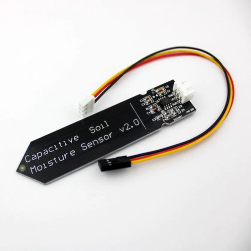
Halo, Semuanya!, bertemui lagi dengan saya yang udah lama nggak nulis karena libur sekolah. Dalam dunia pertanian, pemantauan kelembaban tanah menjadi sangat penting untuk meningkatkan menjaga kesehatan tanaman dan efisiensi penggunaan air . Disini kita kan menggunakan sensor kelembaban tanah kapasitif untuk melakukan pemantauan kondisi tanah tempat tanaman kita. Dalam postingan ini, kita akan membahas bagaimana cara membuat antarmuka sensor kelembaban tanah kapasitif menggunakan Arduino UNO. Project ini nantinya bisa dikembangkan sedemikain rupa untuk mendukung sistem pertanian yang modern. Yuk, kita mulai!

Sensor Kelembaban Tanah Kapasitif

Sensor kelembaban tanah kapasitif adalah alat yang digunakan untuk mengukur kadar kelembaban tanah dengan cara mengukur perubahan kapasitansi listrik disekitar tanah. Sensor ini lebih akurat dan tahan lama dibandingkan dengan sensor kelembaban resistif (yang memiliki 2 probe), sehingga sangat cocok untuk penggunaan jangka panjang.

Untuk dapat mengendalikan input dari sensor ini, kita akan menggunakan Arduino sebagai otaknya. Untuk itu kita perlu mempersiapkan alat, bahan, gambar rangkaian dan contoh codingnya.

Alat dan Bahan

Alat/BahanKebutuhan
Arduino UNO1 Buah
Sensor Kelembaban Tanah Kapasitif1 buah
Layar LCD1 buah
Breadboard1 buah
kabel jumper / kabel biasasecukupnya

Gambar Rangkaian

Instalasi Library LCD 16×2 I2C

untuk bisa mengendalikan sensor LCD 16×2 dengan mudah, kita perlu menginstal library untuk kedua modul tersebut dengan mengikuti langkah-langkah berikut ini:

Bukalah aplikasi Arduino IDE, lalu buka library manager yang terdapat disebelah kiri layar

Library yang akan kita instal adalah library LiquidCrystal_I2C. Gunakan kotak pencarian untuk mempermudah pencarian library yang dimaksud. Lewati langkah ini jika library sudah pernah diinstal sebelumnya.

Setelah library berhasil terinstal, maka kita bisa lanjut ke proses penulisan code program. yukk lanjut…

Coding

/* Gantilah nilai-nilai variabel dibawah ini sesuai dengan hasil pemantauan mu */
#define nilaiBasah 277   // nilai maksimal, kita anggap ini sebagai kondisi basah
#define nilaiKering 380   // nilai minimal, kita anggap sebagai kering

// pin yang terhubung ke sensor
#define sensorPin A0

//library LCD
#include <LiquidCrystal_I2C.h>
LiquidCrystal_I2C lcd(0x27, 16, 2);

void setup() {  
  Serial.begin(9600);
  lcd.init();
  lcd.backlight();
  lcd.setCursor(2, 0);
  lcd.print("Please Wait");
  //tunggu 10 detik sebelum sensor aktif
  lcd.setCursor(0, 1);
  for (int a = 10; a >= 0; a--) {
    Serial.println(a);
    lcd.print(">");
    delay(1000);
  }
  lcd.clear();
  Serial.print("Sensor Aktif");
  lcd.setCursor(2, 0);
  lcd.print("Sensor Aktif");
  delay(1000);
  lcd.clear();
}

void loop() {
  // pembacaan input dari sensor
  int lembab = analogRead(sensorPin);
  //menampilkan hasil pembacaan
  Serial.print("Analog output: ");
  Serial.println(lembab);
  
  // penentuan kondisi tanah
  if (lembab < nilaiBasah) {
    Serial.println("Status: tanah terlalu basah");
    lcd.setCursor(0, 0);
    lcd.print("Kondisi Tanah");
    lcd.setCursor(0, 1);
    lcd.print("terlalu Basah");
  } else if (lembab >= nilaiBasah && lembab < nilaiKering) {
    Serial.println("Status: sempurna");
    lcd.setCursor(0, 0);
    lcd.print("Kondisi Tanah");
    lcd.setCursor(0, 1);
    lcd.print("sempurna");
  } else {
    Serial.println("Status: Tanah terlalu kering, perlu disiram");
    lcd.setCursor(0, 0);
    lcd.print("Kondisi Tanah");
    lcd.setCursor(0, 1);
    lcd.print("terlalu Kering");
  }
  Serial.println();
  delay(1000);
  lcd.clear();
}

Upload kode diatas, cek dahulu pastikan tidak ada yang error. Setelah upload berhasil, kita bisa langsung uji coba dengan menggunakan sampel tanah basah dan kering.

Sampai disini dulu, selamat mencoba.

Membuat Robot Line Follower dengan 5 sensor IR dan motor shield L293D

Membuat Robot Line Follower dengan 5 sensor IR dan motor shield L293D

Assalamualaikum, bertemu lagi di web saya yang sederhana ini. Kali ini saya akan berbagi cara membuat robot line follower dengan menggunakan Arduino, 5 buah sensor infra merah dan motor shield L293D. Robot ini akan berjalan mengikuti jalur berwarna hitam diatas lantai yang berwarna terang. OK, tanpa panjang lebar lagi kita sediakan bahan-bahannya:

Bahan-bahan

NoBahanJumlahGambarLink Pembelian
1Arduino Uno / Arduino Mega1 buahhttps://tokopedia.link/5LTV65Bj8Kb
2Sensor Infra Red5 buahhttps://tokopedia.link/3XxhVMxj8Kb
3Push Button1 buah
4L293D Motor Shield1 buahhttps://tokopedia.link/qzFY1LFj8Kb
5Chassis Robot + motor1 sethttps://tokopedia.link/KMoIvqDj8Kb
6Rumah baterai 18650 2 slot seri1 buah
7Baterai 186502 buah
8Kabel jumper Secukupnya
9acrylic 2 mmsecukupnya

Gambar rangkaian

ikutilah gambar rangkaian dibawah ini. Arduino tidak terlihat didalam gambar karena motorshield akan digabung dengan Arduino dan semua wiring dihubungkan ke motor shield. Saya menggunakan Arduino Mega sebagai mikrokontroler, namun kalian tetap bisa menggunakan Arduino UNO seperti pada gambar.

supaya pin A0 sampai A5 dapat digunakan, pasangkan pin header di barisan lubang dekat posisi pin analog in pada motor shield. Pemasangan pin header ini juga mempermudah kita mengakses 5V dan GND.

Code

#include <AFMotor.h>     //Adafruit Motor Shield Library.
#include <QTRSensors.h>  //Pololu QTR Sensor Library versi 3.1.0.

AF_DCMotor motor1(2);  //konektor M2
AF_DCMotor motor2(1);  //konektor M1


#define KP 0.2  //naikkan nilainya perlahan-lahan untuk menambah keakuraran gerakan robot
#define KD 0.7
#define M1_minumum_speed 200   //motor 1 min speed, perlu diatur masing-masing terutama jika kecepatan putaran roda tidak sama
#define M2_minumum_speed 200   //motor 2 min speed
#define M1_maksimum_speed 255  //motor 1 max speed
#define M2_maksimum_speed 255  //motor 2 max speed
#define NUM_SENSORS 5          //jumlah sensor
#define TIMEOUT 2500
#define EMITTER_PIN 2
#define DEBUG 1
const int buttonPin1 = A0;


int buttonPushCounter = 0;
int buttonState = 0;
int lastButtonState = 0;

QTRSensorsRC qtrrc((unsigned char[]){ A5, A4, A3, A2, A1 }, NUM_SENSORS, TIMEOUT, EMITTER_PIN);

unsigned int sensorValues[NUM_SENSORS];

void setup() {
  Serial.begin(9600);
  pinMode(buttonPin1, INPUT_PULLUP);
  delay(3000);
}

int lastError = 0;
int last_proportional = 0;
int integral = 0;

void loop() {
  buttonState = digitalRead(buttonPin1);
  if (buttonState != lastButtonState) {
    if (buttonState == LOW) {
      buttonPushCounter++;
      buttonState++;
      Serial.println(buttonPushCounter);
      Serial.println(buttonState);

    } else {
      Serial.println("off");
    }
    delay(100);
  }
  lastButtonState = buttonState;

  if (buttonPushCounter == 1) {
    Serial.println("calibrating");
    manual_calibration();
    Serial.println("Stop");
    motor1.run(RELEASE);
    motor2.run(RELEASE);
    motor1.setSpeed(0);
    motor2.setSpeed(0);
    buttonPushCounter = 2;
  }

  if (buttonPushCounter == 3) {
    unsigned int sensors[5];
    int position = qtrrc.readLine(sensors);
    int error = position - 2000;
    Serial.print("error: ");
    Serial.print(error);
    Serial.print(" ");

    int motorSpeed = KP * error + KD * (error - lastError);  //1 x 2000 +
    lastError = error;
    int leftMotorSpeed = M1_minumum_speed + motorSpeed;
    int rightMotorSpeed = M2_minumum_speed - motorSpeed;
    Serial.print(motorSpeed);
    Serial.print(", ");
    Serial.print(leftMotorSpeed);
    Serial.print(", ");
    Serial.print(rightMotorSpeed);
    set_motors(leftMotorSpeed, rightMotorSpeed);
  }

  if (buttonPushCounter == 4) {
    Serial.println("Stop");
    motor1.run(RELEASE);
    motor2.run(RELEASE);
    motor1.setSpeed(0);
    motor2.setSpeed(0);
    buttonPushCounter = 2;
  }
}

void set_motors(int motor1speed, int motor2speed) {
  if (motor1speed > M1_maksimum_speed) motor1speed = M1_maksimum_speed;
  if (motor2speed > M2_maksimum_speed) motor2speed = M2_maksimum_speed;
  if (motor1speed < 0) motor1speed = 0;
  if (motor2speed < 0) motor2speed = 0;
  motor1.setSpeed(motor1speed);
  Serial.print("speed kiri: ");
  Serial.print(motor1speed);
  motor2.setSpeed(motor2speed);
  Serial.print(" | speed kanan: ");
  Serial.println(motor2speed);

  motor1.run(FORWARD);
  motor2.run(FORWARD);
}

void manual_calibration() {
  int i;
  for (i = 0; i < 250; i++) {
    if (i <= 25 || i >= 75) {
      motor1.run(FORWARD);
      motor2.run(BACKWARD);
      motor1.setSpeed(100);
      motor2.setSpeed(100);
    } else {
      motor1.run(BACKWARD);
      motor2.run(FORWARD);
      motor1.setSpeed(100);
      motor2.setSpeed(100);
    }
    qtrrc.calibrate(QTR_EMITTERS_ON);
    delay(20);
  }


  if (DEBUG) {
    Serial.begin(9600);
    for (int i = 0; i < NUM_SENSORS; i++) {
      Serial.print(qtrrc.calibratedMinimumOn[i]);
      Serial.print(' ');
    }
    Serial.println();

    for (int i = 0; i < NUM_SENSORS; i++) {
      Serial.print(qtrrc.calibratedMaximumOn[i]);
      Serial.print(' ');
    }
  }
}

Foto-Foto

untuk memeprmudah proses perakitan, saya lampirkan foto-foto robot dari segala sisi. Di sini saya menggunakan Arduino Mega sebagai mikrokontroler

Selanjutnya, kita coba menjalankan robot di jalur garis yang terbuat dari isolasi listrik atau lakban hitam. Selamat mencoba

Membuat Jam Digital Dengan Menggunakan LED Matrix, RTC & Arduino Nano

Membuat Jam Digital Dengan Menggunakan LED Matrix, RTC & Arduino Nano

Assalamualaikum, Semoga kalian semua selalu dalam keadaan sehat wal afiat.

Lewat tulisan kali ini, saya akan memberikan tutorial singkat tentang cara membuat Jam Digital dengan menggunakan LED Matrix dan RTC. Untuk sistem kendalinya, saya akan menggunakan Arduino Nano. Jika kamu tidak memiliki Arduino Nano, kamu tetap bisa menggunakan Arduino jenis lainnya, misalnya Arduino Uno.

Proses visual dari tutorial ini bisa kamu lihat di channel youtube saya dibawah ini:

Bahan-bahan

Sebelum kita mulai proses perakitan, tentu saja kita harus mempersiapkan bahan-bahan untuk proyek kita kali ini.

BahanKebutuhan
Arduino Nano1 buah
RTC DS13071 buah
LED Matrix Max 7219 4 matrix1 buah
tactile button2 buah
Photo Resistor /LDR1 buah
Resistor 10 K ohm1 buah
Kabelsecukupnya

Gambar Rangkaian

Library

Sebelum kita memasukkan program / coding jam digitalnya ke Arduino nano, kita harus menginstal beberapa library terlebih dahulu. library-library yang dibutuhkan untuk alat yang kita buat sekarang ini bisa kamu download lewat link di bawah ini:

https://drive.google.com/drive/folders/1II3iu1tUfJFumAQNPWqzRLYnI0zBZz2_?usp=sharing

Setelah semua library berhasil di download, buka Arduino IDE lalu ke menu sketch >> include library >> add .ZIP library lalu pilih file library yang telah kita download sebelumnya.

Coding

Setelah semua library terinstal dengan baik, kita sudah bisa menuliskan program untuk jam digital ini di Arduino IDE. Coding nya bisa kamu lihat dibawah ini

//include libraries:
#include "LedControl.h"                  // For assigning LED's
#include <fontDigiClock.h>               // Font library
#include <Wire.h>                        // DS1307 clock
#include "RTClib.h"                      // DS1307 clock, works also with DS3231 clock
#include <Button.h>                      // Button library by Alexander Brevig
#include <OneWire.h>                     // This library allows you to communicate with I2C                   

//define constants
#define NUM_DISPLAY_MODES 5              // Number of clock-modes  (counting zero as the first mode)
#define NUM_SETTINGS_MODES 3             // Number of settings modes = 3 (conting zero as the first mode)
#define SLIDE_DELAY 55                   // The time in milliseconds for the slide effect per character in slide mode. Make this higher for a slower effect
#define cls   clear_display              // Clear display

#define LIGHT A0                         // Photoresistor (LDR) for steering brightness
#define ONE_WIRE_BUS 4                   // Data wire is plugged into pin 4 on the Arduino
OneWire oneWire(ONE_WIRE_BUS);           // Setup a oneWire instance to communicate with any OneWire devices (not just Maxim/Dallas temperature ICs)

// Setup LED Matrix
// pin 12 is connected to the DataIn (DIN) on the display
// pin 11 is connected to the CLK on the display
// pin 10 is connected to LOAD (CS) on the display

//sets the 3 pins as 12, 11 & 10 and then sets 4 displays (max is 8 displays)
LedControl lc = LedControl(12, 11, 10, 4);

//global variables
bool debug = true;                      // For debugging only, starts serial output (true/false)
bool show_intro = true;                  // Show intro at startup ?  (true/false)
byte intensity = 0;                      // Startup intensity/brightness (0-15)
bool ampm = false;                       // Define 12 or 24 hour time. false = 24 hour. true = 12 hour
bool show_date = true;                   // Show date? - Display date approx. every 2 minutes (default = true)
bool circle = true;                      // Define circle mode - changes the clock-mode approx. every 2 minutes. Default = true (on)
byte clock_mode = 1;                     // Default clock mode.
                                         // clock_mode 0 = basic mode 
                                         // clock_mode 1 = small mode
                                         // clock_mode 2 = slide mode
                                         // clock_mode 3 = smallslide mode                                          
                                         // clock_mode 4 = word clock
                                         // clock_mode 5 = shift mode
                                         // clock_mode 6 = setup menu
////________________________________________________________________________________________
//Please don't change the following variables:                                                                                                                      
byte old_mode = clock_mode;              // Stores the previous clock mode, so if we go to date or whatever, we know what mode to go back.
short DN;                                // Returns the number of day in the year
short WN;                                // Returns the number of the week in the year
bool date_state = true;                  // Holds state of displaying date 
int devices, dev;                        // Number of LED Matrix-Displays (dev = devices-1)
int rtc[7];                              // Array that holds complete real time clock output
char tempi[4];                           // Holds temperature-chars for displaying temp
char dig[7];                             // Holds time-chars for shift-mode
char shiftChar[8];                       // Holds chars to display in shift-mode
////________________________________________________________________________________________


//day array  (The DS1307/DS3231 outputs 1-7 values for day of week)
char days[7][4] = {
  "Ming", "Sen", "Sel", "Rab", "Kam", "Jum", "Sab"
};
char daysfull[7][9] = {
  "Minggu", "Senin", "Selasa", "Rabu", "Kamis", "Jumat", "Sabtu"
};
char suffix[1] = {'.'};                  //date suffix "." , used in slide, basic and jumble modes - e.g. date = 25.
                                         //suffix in German is always "."


RTC_DS1307 ds1307;                       // Create RTC object - works also with DS3231

Button buttonA = Button(2, BUTTON_PULLUP);      // Setup button A (using button library)
Button buttonB = Button(3, BUTTON_PULLUP);      // Setup button B (using button library)

////////////////////////////////////////////////////////////////////////////////////////

void setup() {
  digitalWrite(2, HIGH);                 // turn on pullup resistor for button on pin 2
  digitalWrite(3, HIGH);                 // turn on pullup resistor for button on pin 3
  pinMode(LIGHT, INPUT);                 // LDR for brightness
 
  if(debug){
  Serial.begin(9600); //start serial
  Serial.println("Debugging activated ... ");
  }
  
  //initialize the 4 matrix panels
  //we have already set the number of devices when we created the LedControl
  devices = lc.getDeviceCount();
  dev = devices-1;
  
  //we have to init all devices in a loop
  for (int address = 0; address < devices; address++) {
    /*The MAX72XX is in power-saving mode on startup*/
    lc.shutdown(address, false);
    /* Set the brightness to a medium values */
    lc.setIntensity(address, intensity);
    /* and clear the display */
    lc.clearDisplay(address);
  }

  //Setup DS1307/DS3231 RTC
  #ifdef AVR
  Wire.begin();    // start I2C communication
  #else
  Wire1.begin();   // Shield I2C pins connect to alt I2C bus on Arduino
  #endif
  ds1307.begin();  //start RTC Clock - works also with DS3231
 
 /* if (! ds1307.isrunning()) {
    Serial.println("RTC is NOT running!");
    ds1307.adjust(DateTime(__DATE__, __TIME__));  // sets the RTC to the date & time this sketch was compiled
  }
*/

 //Show intro ?
 if(show_intro){ intro(); }

 wipeBottom();

 // Show state of displaying date. toggleDateState() must! run once at startup, otherwise it shows opposite information.
 toggleDateState();

} // end of setup

////////////////////////////////////////////////////////////////////////////////////////

void loop() {
  
  //run the clock with whatever mode is set by clock_mode - the default is set at top of code.
  switch (clock_mode){       
  case 0: 
    basic();
    break; 
  case 1: 
    small(); 
    break;
  case 2: 
    slide(); 
    break;
  case 3: 
    smallslide(); 
    break;  
  case 4: 
    word_clock(); 
    break;
  case 5: 
    shift(); 
    break;
  case 6: 
    setup_menu(); 
    break;
  }

  
} // end of loop


////////////////////////////////////////////////////////////////////////////////////////

// plot: plot a dot at positon xy with val 0/1 
void plot (byte x, byte y, byte val) {
  y=7-y;
  //select which matrix depending on the x coord
  byte address;
  if (x >= 0 && x <= 7)   {
    address = 3;
  }
  if (x >= 8 && x <= 15)  {
    address = 2;
    x = x - 8;
  }
  if (x >= 16 && x <= 23) {
    address = 1;
    x = x - 16;
  }
  if (x >= 24 && x <= 31) {
    address = 0;
    x = x - 24;
  }

  if (val == 1) {
    lc.setLed(address, 7-y, x, true);
  } else {
    lc.setLed(address, 7-y, x, false);
  }
}


////////////////////////////////////////////////////////////////////////////////////////

//clear screen
void clear_display() {
  for (byte address = 0; address < 4; address++) {
    lc.clearDisplay(address);
  }
}

////////////////////////////////////////////////////////////////////////////////////////

// setBright: set the brightness to a value between 0 and 15 (= 16 steps, in dependence of LDR)
int setBright(){
  // map LDR-values from 0 to 15 and set the brightness of devices
  int brightness = map(analogRead(LIGHT), 0, 1023, 0, 15);

  //we have to init all devices in a loop
  for (int address = 0; address < devices; address++) {
    lc.setIntensity(address, brightness);
  }
  return brightness;
}

////////////////////////////////////////////////////////////////////////////////////////

// fade_high: fade intensity from 0 to brightness (in dependence of LDR)
void fade_high() {

  // map LDR-values from 0 to 15
  int brightness = map(analogRead(LIGHT), 0, 1023, 0, 15);
  
  //fade from intensity 0 to brightness and set the brightness of devices
  for (byte f=0; f<=brightness; f++) {
    for (byte address = 0; address < 4; address++) {
      lc.setIntensity(address, f);
    }
    delay(120); //change this to alter fade-up speed
  }
  return;
}

////////////////////////////////////////////////////////////////////////////////////////
// fade_low: fade intensity from brightness (in dependence of LDR) to 0
void fade_low() {

  // map LDR-values from 0 to 15
  int brightness = map(analogRead(LIGHT), 0, 1023, 0, 15);
 
  //fade from brightness to 1 and set the brightness of devices
  for (byte f=brightness; f>0; f--) {
    for (byte address = 0; address < 4; address++) {
      lc.setIntensity(address, f);
    }
    delay(120); //change this to alter fade-low speed
  }  
  for (byte address = 0; address < 4; address++) {
    lc.setIntensity(address, 0);  // set intensity to lowest level
  }
  return;
}

////////////////////////////////////////////////////////////////////////////////////////

//intro: show intro at startup
void intro() {

  for (byte address = 0; address < 4; address++) {
       lc.setIntensity(address, 3);
  }

  for(int i=0; i<2; i++){
      wipeBottom();
      wipeTop();
  }
  wipeOutside();


  char ver_a[9] = " Helmy"; 
  char ver_b[9] = " Aswan";
  char ver_c[9] = " Daniel";

  for (byte address = 0; address < 4; address++) {
       lc.setIntensity(address, 0);
  }

 byte i = 0;
  while (ver_a[i]) {
    delay(80);
    puttinychar((i * 4), 1, ver_a[i]);
    i++;
  }
  fade_high();
  delay(200);
  fade_low();
  delay(500);
  wipeOutside();

  i = 0;
  while (ver_b[i]) {
    delay(80);
    puttinychar((i * 4), 1, ver_b[i]);
    i++;
  } 
  fade_high();
  delay(200);
  fade_low(); 
  delay(500);
  wipeMiddle();
  i = 0;
  while (ver_c[i]) {
    delay(80);
    puttinychar((i * 4), 1, ver_c[i]);
    i++;
  }
  fade_high();
  delay(200);
  fade_low();
  delay(500);
  wipeOutside();

} // end of intro

////////////////////////////////////////////////////////////////////////////////////////

// puttinychar:
// Copy a 3x5 character glyph from the myfont data structure to display memory, with its upper left at the given coordinate
// This is unoptimized and simply uses plot() to draw each dot.
void puttinychar(byte x, byte y, char c){
  byte dots;
  if (c >= 'A' && c <= 'Z' || (c >= 'a' && c <= 'z') ) {
    c &= 0x1F;   // A-Z maps to 1-26
  }
  else if (c >= '0' && c <= '9') {
    c = (c - '0') + 32;
  }
  else if (c == ' ') {
    c = 0; // space
  }
  else if (c == '.') {
    c = 27; // full stop
  }
  else if (c == ':') {
    c = 28; // colon
  }
  else if (c == '\'') {
    c = 29; // single quote mark
  }
  else if (c == '!') {
    c = 30; // exclamation mark
  }
  else if (c == '?') {
    c = 31; // question mark
  }
  else if (c == '-') {
    c = 42; // hyphen
  }
  else if (c == '#') {
    c = 43; // degree-symbol
  }
  else if (c == '>') {
    c = 44; // selector-arrow
  }
  else if (c == '~') {
    c = 45; // Ü
  }
  else if (c == '*') {
    c = 46; // Ö
  }


  for (byte col = 0; col < 3; col++) {
    dots = pgm_read_byte_near(&mytinyfont[c][col]);
    for (char row = 0; row < 5; row++) {
      if (dots & (16 >> row))
        plot(x + col, y + row, 1);
      else
        plot(x + col, y + row, 0);
    }
  }
}

////////////////////////////////////////////////////////////////////////////////////////

//putnormalchar:
//Copy a 5x7 character glyph from the myfont data structure to display memory
void putnormalchar(byte x, byte y, char c){
  byte dots;
  if (c >= 'A' && c <= 'Z' ) {
    c &= 0x1F;   // A-Z maps to 1-26
  }
  else if (c >= 'a' && c <= 'z') {
    c = (c - 'a') + 41;   // A-Z maps to 41-67
  }
  else if (c >= '0' && c <= '9') {
    c = (c - '0') + 31;
  }
  else if (c == ' ') {
    c = 0; // space
  }
  else if (c == '.') {
    c = 27; // full stop
  }
  else if (c == '\'') {
    c = 28; // single quote mark
  }
  else if (c == ':') {
    c = 29; // colon
  }
  else if (c == '>') {
    c = 30; // clock_mode selector arrow
  }
  else if (c == '=') {
    c = 79; // equal sign
  }

  
  else if (c >= -80 && c <= -67) {
    c *= -1;
  }

  for (char col = 0; col < 5; col++) {
    dots = pgm_read_byte_near(&myfont[c][col]);
    for (char row = 0; row < 7; row++) {
      //check coords are on screen before trying to plot
      //if ((x >= 0) && (x <= 31) && (y >= 0) && (y <= 7)){

      if (dots & (64 >> row)) {   // only 7 rows.
        plot(x + col, y + row, 1);
      } else {
        plot(x + col, y + row, 0);
      }
      //}
    }
  }
}

////////////////////////////////////////////////////////////////////////////////////////

// small(=mode 1): show the time in small 3x5 characters with seconds-dots at bottom-line
void small() {
  char textchar[8]; // the 16 characters on the display
  byte mins = 100; //mins
  byte secs = rtc[0]; //seconds
  byte old_secs = secs; //holds old seconds value - from last time seconds were updated o display - used to check if seconds have changed
  
  cls();

  //run clock main loop as long as run_mode returns true
  while (run_mode()) {
  get_time();
  secs = rtc[0];

  //check for button presses
  if (buttonA.uniquePress()) { switch_mode();  return; }
  if (buttonB.uniquePress()) { toggleDateState();  delay(1000); return; }


  // when in circle mode and minute=even and second=14, switch to word_clock (mode 4)
  if(circle){
    if(rtc[1] % 2 == 0 && rtc[0]==14){
       wipeInside();
       clock_mode =4;  // switch to wordclock mode
       return;
    }
  }


  //if secs changed then update them on the display
  if (secs != old_secs) {

  bottomleds(secs); // plot seconds-dots at bottomline

  // display date, when second=40  and date_state = true
  if(rtc[0]==40  && date_state){
     display_date();
     return;    
    }
      
      char buffer[3];
      itoa(secs, buffer, 10);

      //fix - as otherwise if num has leading zero, e.g. "03" secs, itoa coverts this to chars with space "3 ".
      if (secs < 10) {
        buffer[1] = buffer[0];
        buffer[0] = '0';
      }

      puttinychar( 20, 1, ':'); //seconds colon
      puttinychar( 24, 1, buffer[0]); //seconds
      puttinychar( 28, 1, buffer[1]); //seconds
      old_secs = secs;
    }

    //if minute changes change time
    if (mins != rtc[1]) {

      //reset these for comparison next time
      mins = rtc[1];
      byte hours = rtc[2];
      if (hours > 12) {
        hours = hours - ampm * 12;
      }
      if (hours < 1) {
        hours = hours + ampm * 12;
      }


      //byte dow  = rtc[3]; // the DS1307/DS3231 outputs 0 - 6 where 0 = Sunday0 - 6 where 0 = Sunday.
      //byte date = rtc[4];

      //set characters
      char buffer[3];
      itoa(hours, buffer, 10);

      //fix - as otherwise if num has leading zero, e.g. "03" hours, itoa coverts this to chars with space "3 ".
      if (hours < 10) {
        buffer[1] = buffer[0];
        //if we are in 12 hour mode blank the leading zero.
        if (ampm) {
          buffer[0] = ' ';
        }
        else {
          buffer[0] = '0';
        }
      }
      //set hours chars
      textchar[0] = buffer[0];
      textchar[1] = buffer[1];
      textchar[2] = ':';

      itoa (mins, buffer, 10);
      if (mins < 10) {
        buffer[1] = buffer[0];
        buffer[0] = '0';
      }
      //set mins characters
      textchar[3] = buffer[0];
      textchar[4] = buffer[1];

      //do seconds
      textchar[5] = ':';
      buffer[3];
      secs = rtc[0];
      itoa(secs, buffer, 10);

      //fix - as otherwise if num has leading zero, e.g. "03" secs, itoa coverts this to chars with space "3 ".
      if (secs < 10) {
        buffer[1] = buffer[0];
        buffer[0] = '0';
      }
      //set seconds
      textchar[6] = buffer[0];
      textchar[7] = buffer[1];

      byte x = 0;
      byte y = 0;

      //print each char
      for (byte x = 0; x < 6 ; x++) {
        puttinychar( x * 4, 1, textchar[x]);
      }
    }
    delay(50);
  } // end of while run_mode
}


////////////////////////////////////////////////////////////////////////////////////////

// basic(= mode 0): simple mode shows the time in 5x7 characters
void basic(){
  cls();

  char buffer[3];   //for int to char conversion to turn rtc values into chars we can print on screen
  byte offset = 0;  //used to offset the x postition of the digits and centre the display when we are in 12 hour mode and the clock shows only 3 digits. e.g. 3:21
  byte x, y;        //used to draw a clear box over the left hand "1" of the display when we roll from 12:59 -> 1:00am in 12 hour mode.

  //do 12/24 hour conversion if ampm set to 1
  byte hours = rtc[2];

  if (hours > 12) {
    hours = hours - ampm * 12;
  }
  if (hours < 1) {
    hours = hours + ampm * 12;
  }

  //do offset conversion
  if (ampm && hours < 10) {
    offset = 2;
  }
  else{
    offset = 0;
  }
  
  //set the next minute we show the date at
  //set_next_date();
  
  // initially set mins to value 100 - so it wll never equal rtc[1] on the first loop of the clock, meaning we draw the clock display when we enter the function
  byte secs = 100;
  byte mins = 100;
  int count = 0;
  
  //run clock main loop as long as run_mode returns true
  while (run_mode()) {

    //get the time from the clock chip
    get_time();
   
    //check for button press
    if (buttonA.uniquePress()) { switch_mode(); return;  }
    if (buttonB.uniquePress()) { toggleDateState();  delay(1000); return; }


    // display temp, when second=40 and minute=even and date_state=true
    if(rtc[0]==40 && rtc[1] % 2 == 0 && date_state){
       wipeBottom();
       wipeTop();
       return; 
      }
      
    // display date, when second=40 and minute=odd and date_state = true
    if(rtc[0]==40 && rtc[1] % 2 == 1 && date_state){
       display_date();
       return;    
      }

    //draw the flashing colon on/off if the secs have changed.
    if (secs != rtc[0]) {     
       secs = rtc[0];  //update secs with new value
   
      //Blink "::"
      if(secs % 2 == 0){
        plot(14-offset, 4, 1);
        plot(14-offset, 2, 0);
        plot(16-offset, 4, 0);
        plot(16-offset, 2, 1);
      }
      else {
        plot(14-offset, 4, 0);
        plot(14-offset, 2, 1);
        plot(16-offset, 4, 1);
        plot(16-offset, 2, 0);
      }
    }
   
    //redraw the display if button pressed or if mins != rtc[1]
    if (mins != rtc[1]) {

      //update mins and hours with the new values
      mins = rtc[1];
      hours = rtc[2];

      //adjust hours of ampm set to 12 hour mode
      if (hours > 12) { hours = hours - ampm * 12; }
      if (hours < 1) { hours = hours + ampm * 12;  }

      itoa(hours, buffer, 10);

      //if hours < 10 the num e.g. "3" hours, itoa coverts this to chars with space "3 " which we dont want
      if (hours < 10) {
        buffer[1] = buffer[0];
        buffer[0] = '0';
      }

      //print hours
      //if we in 12 hour mode and hours < 10, then don't print the leading zero, and set the offset so we centre the display with 3 digits.
      if (ampm && hours < 10) {
        offset = 2;

        //if the time is 1:00am clear the entire display as the offset changes at this time and we need to blank out the old 12:59
        if ((hours == 1 && mins == 0) ) {
          cls();
        }
      }
      else {
        //else no offset and print hours tens digit
        offset = 0;
        
              //if the time is 10:00am clear the entire display as the offset changes at this time and we need to blank out the old 9:59
              if (hours == 10 && mins == 0) {
              cls();
              }
              
         putnormalchar(1,  0, buffer[0]);
      }
      
      //print hours ones digit
      putnormalchar(7 - offset, 0, buffer[1]);

      //print mins
      //add leading zero if mins < 10 
      itoa (mins, buffer, 10);
      if (mins < 10) {
        buffer[1] = buffer[0];
        buffer[0] = '0';
      }
      //print mins tens and mins ones digits
      putnormalchar(19 - offset, 0, buffer[0]);
      putnormalchar(25 - offset, 0, buffer[1]);
    } // end of if (mins != rtc[1]
  } // end of while run_mode
}

////////////////////////////////////////////////////////////////////////////////////////

//Big-Slide mode (=mode 2): like basic-mode, but with sliding digits top-down
void slide() {
  byte digits_old[4] = {99, 99, 99, 99}; //old values  we store time in. Set to somthing that will never match the time initially so all digits get drawn wnen the mode starts
  byte digits_new[4]; //new digits time will slide to reveal
  byte digits_x_pos[4] = {25, 19, 7, 1}; //x pos for which to draw each digit at

  char old_char[2]; //used when we use itoa to transpose the current digit (type byte) into a char to pass to the animation function
  char new_char[2]; //used when we use itoa to transpose the new digit (type byte) into a char to pass to the animation function

  //old_chars - stores the 5 day and date suffix chars on the display. e.g. "mon" and "st". We feed these into the slide animation as the current char when these chars are updated.
  //We sent them as A initially, which are used when the clocl enters the mode and no last chars are stored.
  //char old_chars[6] = "AAAAA";

  cls();
  
  // plot the clock colon on the display
  //  putnormalchar( 13, 0, ':');

  byte old_secs = rtc[0]; //store seconds in old_secs. We compare secs and old secs. WHen they are different we redraw the display

  //run clock main loop as long as run_mode returns true
  while (run_mode()) {

    get_time();
    byte secs =rtc[0];


  // display date, when second=40 and date_state = true
  if(rtc[0]==40 && date_state){
     display_date();
     return;    
    }
      

  // when in circle mode and minute=even and second=15, switch to shift mode (mode 5)
  if(circle){
    if(rtc[1] % 2 == 0 && rtc[0]==15){
       wipeMiddle();
       wipeTop();
       clock_mode =5;  // switch to shift mode
       return;
    }
  }
    
    //check for button press
    if (buttonA.uniquePress()) { switch_mode();  return; }
    if (buttonB.uniquePress()) { toggleDateState();  delay(1000); return; }

    //if secs have changed then update the display
    if (rtc[0] != old_secs) {

      //Blink "::"
      if(old_secs % 2 == 0){       
        plot(14, 4, 1);
        plot(14, 2, 1);       
        plot(16, 4, 0);
        plot(16, 2, 0);         
      }
      else {
        plot(16, 4, 1);
        plot(16, 2, 1);
        plot(14, 4, 0);
        plot(14, 2, 0);       
      }
     
      old_secs = rtc[0];

      //do 12/24 hour conversion if ampm set to 1
      byte hours = rtc[2];
      if (hours > 12) {
        hours = hours - ampm * 12;
      }
      if (hours < 1) {
        hours = hours + ampm * 12;
      }

      //split all date and time into individual digits - stick in digits_new array

      //rtc[0] = secs                        //array pos and digit stored
      //digits_new[0] = (rtc[0]%10);           //0 - secs ones
      //digits_new[1] = ((rtc[0]/10)%10);      //1 - secs tens
      //rtc[1] = mins
      digits_new[0] = (rtc[1] % 10);         //2 - mins ones
      digits_new[1] = ((rtc[1] / 10) % 10);  //3 - mins tens
      //rtc[2] = hours
      digits_new[2] = (hours % 10);         //4 - hour ones
      digits_new[3] = ((hours / 10) % 10);  //5 - hour tens
      //rtc[4] = date
      //digits_new[6] = (rtc[4]%10);           //6 - date ones
      //digits_new[7] = ((rtc[4]/10)%10);      //7 - date tens

      //draw initial screen of all chars. After this we just draw the changes.

      //compare digits 0 to 3 (mins and hours)
      for (byte i = 0; i <= 3; i++) {
        //see if digit has changed...
        if (digits_old[i] != digits_new[i]) {

          //run 9 step animation sequence for each in turn
          for (byte seq = 0; seq <= 8 ; seq++) {

            //convert digit to string
            itoa(digits_old[i], old_char, 10);
            itoa(digits_new[i], new_char, 10);

            //if set to 12 hour mode and we're on digit 2 (hours tens mode) then check to see if this is a zero. If it is, blank it instead so we get 2.00pm not 02.00pm
            if (ampm && i == 3) {
              if (digits_new[3] == 0) {
                new_char[0] = ' ';
              }
              if (digits_old[3] == 0) {
                old_char[0] = ' ';
              }
            }
            //draw the animation frame for each digit
            slideanim(digits_x_pos[i], 0, seq, old_char[0], new_char[0]);
            delay(SLIDE_DELAY);
          }
        }
      }

 
      //save digita array tol old for comparison next loop
      for (byte i = 0; i <= 3; i++) {
        digits_old[i] =  digits_new[i];
      }
    }// end of secs/oldsecs
  }// end of while run_mode
}

////////////////////////////////////////////////////////////////////////////////////////

//called by slide
//this draws the animation of one char sliding on and the other sliding off. There are 8 steps in the animation, we call the function to draw one of the steps from 0-7
//inputs are are char x and y, animation frame sequence (0-7) and the current and new chars being drawn.
void slideanim(byte x, byte y, byte sequence, char current_c, char new_c) {

  //  To slide one char off and another on we need 9 steps or frames in sequence...

  //  seq# 0123456 <-rows of the display
  //   |   |||||||
  //  seq0 0123456  START - all rows of the display 0-6 show the current characters rows 0-6
  //  seq1  012345  current char moves down one row on the display. We only see it's rows 0-5. There are at display positions 1-6 There is a blank row inserted at the top
  //  seq2 6 01234  current char moves down 2 rows. we now only see rows 0-4 at display rows 2-6 on the display. Row 1 of the display is blank. Row 0 shows row 6 of the new char
  //  seq3 56 0123
  //  seq4 456 012  half old / half new char
  //  seq5 3456 01
  //  seq6 23456 0
  //  seq7 123456
  //  seq8 0123456  END - all rows show the new char

  //from above we can see...
  //currentchar runs 0-6 then 0-5 then 0-4 all the way to 0. starting Y position increases by 1 row each time.
  //new char runs 6 then 5-6 then 4-6 then 3-6. starting Y position increases by 1 row each time.

  //if sequence number is below 7, we need to draw the current char
  if (sequence < 7) {
    byte dots;
    if (current_c >= 'A' && current_c <= 'Z' ) {
      current_c &= 0x1F;   // A-Z maps to 1-26
    }
    else if (current_c >= 'a' && current_c <= 'z') {
      current_c = (current_c - 'a') + 41;   // a-z maps to 41-66
    }
    else if (current_c >= '0' && current_c <= '9') {
      current_c = (current_c - '0') + 31;
    }
    else if (current_c == ' ') {
      current_c = 0; // space
    }
    else if (current_c == '.') {
      current_c = 27; // full stop
    }
    else if (current_c == '\'') {
      current_c = 28; // single quote mark
    }
    else if (current_c == ':') {
      current_c = 29; //colon
    }
    else if (current_c == '>') {
      current_c = 30; // clock_mode selector arrow
    }

    byte curr_char_row_max = 7 - sequence; //the maximum number of rows to draw is 6 - sequence number
    byte start_y = sequence; //y position to start at - is same as sequence number. We inc this each loop

    //plot each row up to row maximum (calculated from sequence number)
    for (byte curr_char_row = 0; curr_char_row <= curr_char_row_max; curr_char_row++) {
      for (byte col = 0; col < 5; col++) {
        dots = pgm_read_byte_near(&myfont[current_c][col]);
        if (dots & (64 >> curr_char_row))
          plot(x + col, y + start_y, 1); //plot led on
        else
          plot(x + col, y + start_y, 0); //else plot led off
      }
      start_y++;//add one to y so we draw next row one down
    }
  }

  //draw a blank line between the characters if sequence is between 1 and 7. If we don't do this we get the remnants of the current chars last position left on the display
  if (sequence >= 1 && sequence <= 8) {
    for (byte col = 0; col < 5; col++) {
      plot(x + col, y + (sequence - 1), 0); //the y position to draw the line is equivalent to the sequence number - 1
    }
  }

  //if sequence is above 2, we also need to start drawing the new char
  if (sequence >= 2) {

    //work out char
    byte dots;
    //if (new_c >= 'A' && new_c <= 'Z' || (new_c >= 'a' && new_c <= 'z') ) {
    //  new_c &= 0x1F;   // A-Z maps to 1-26
    //}
    if (new_c >= 'A' && new_c <= 'Z' ) {
      new_c &= 0x1F;   // A-Z maps to 1-26
    }
    else if (new_c >= 'a' && new_c <= 'z') {
      new_c = (new_c - 'a') + 41;   // A-Z maps to 41-67
    }
    else if (new_c >= '0' && new_c <= '9') {
      new_c = (new_c - '0') + 31;
    }
    else if (new_c == ' ') {
      new_c = 0; // space
    }
    else if (new_c == '.') {
      new_c = 27; // full stop
    }
    else if (new_c == '\'') {
      new_c = 28; // single quote mark
    }
    else if (new_c == ':') {
      new_c = 29; // clock_mode selector arrow
    }
    else if (new_c == '>') {
      new_c = 30; // clock_mode selector arrow
    }

    byte newcharrowmin = 6 - (sequence - 2); //minimumm row num to draw for new char - this generates an output of 6 to 0 when fed sequence numbers 2-8. This is the minimum row to draw for the new char
    byte start_y = 0; //y position to start at - is same as sequence number. we inc it each row

    //plot each row up from row minimum (calculated by sequence number) up to 6
    for (byte newcharrow = newcharrowmin; newcharrow <= 6; newcharrow++) {
      for (byte col = 0; col < 5; col++) {
        dots = pgm_read_byte_near(&myfont[new_c][col]);
        if (dots & (64 >> newcharrow))
          plot(x + col, y + start_y, 1); //plot led on
        else
          plot(x + col, y + start_y, 0); //else plot led off
      }
      start_y++;//add one to y so we draw next row one down
    }
  }
}

////////////////////////////////////////////////////////////////////////////////////////

//Small-Slide-mode (mode 3): like small-mode, but with sliding digits top-down
void smallslide() {
  byte digits_old[6] = {99, 99, 99, 99, 99, 99}; //old values  we store time in. Set to somthing that will never match the time initially so all digits get drawn wnen the mode starts
  byte digits_new[6]; //new digits time will slide to reveal
  byte digits_x_pos[6] = {29, 25, 17, 13, 5, 1}; //x pos for which to draw each digit at

  char old_char[2]; //used when we use itoa to transpose the current digit (type byte) into a char to pass to the animation function
  char new_char[2]; //used when we use itoa to transpose the new digit (type byte) into a char to pass to the animation function
  
  byte old_secs = rtc[0]; //store seconds in old_secs. We compare secs and old secs. WHen they are different we redraw the display
  
  cls();
  
  //run clock main loop as long as run_mode returns true
  while (run_mode()) {
   get_time();

      
  // when in circle mode and minute=odd and second=12, switch to slide mode (mode 2)
  if(circle){
    if(rtc[1] % 2 == 1 && rtc[0]==12){
       wipeInside();
       wipeTop();
       clock_mode =2;  // switch to slide mode
       return;
    }
  }

    //if secs have changed then update the display
    if (rtc[0] != old_secs) {
      old_secs = rtc[0];

      //do 12/24 hour conversion if ampm set to 1
      byte hours = rtc[2];
      if (hours > 12) {
        hours = hours - ampm * 12;
      }
      if (hours < 1) {
        hours = hours + ampm * 12;
      }

      //split all date and time into individual digits - stick in digits_new array
      //rtc[0] = secs                        //array pos and digit stored
      digits_new[0] = (rtc[0]%10);           //0 - secs ones
      digits_new[1] = ((rtc[0]/10)%10);      //1 - secs tens
      //rtc[1] = mins
      digits_new[2] = (rtc[1] % 10);         //2 - mins ones
      digits_new[3] = ((rtc[1] / 10) % 10);  //3 - mins tens
      //rtc[2] = hours
      digits_new[4] = (hours % 10);          //4 - hour ones
      digits_new[5] = ((hours / 10) % 10);   //5 - hour tens
      //rtc[4] = date
      //digits_new[6] = (rtc[4]%10);         //6 - date ones
      //digits_new[7] = ((rtc[4]/10)%10);    //7 - date tens

      //draw initial screen of all chars. After this we just draw the changes.

      //compare digits 0 to 5 (secs, mins and hours)
      for (byte i = 0; i <= 5; i++) {
        //see if digit has changed...
        if (digits_old[i] != digits_new[i]) {

          //run 9 step animation sequence for each in turn
          for (byte seq = 0; seq <= 8 ; seq++) {

            //convert digit to string
            itoa(digits_old[i], old_char, 10);
            itoa(digits_new[i], new_char, 10);

            //if set to 12 hour mode and we're on digit 5 (hours tens mode) then check to see if this is a zero. If it is, blank it instead so we get 2.00pm not 02.00pm
            if (ampm && i == 5) {
              if (digits_new[5] == 0) {
                new_char[0] = ' ';
              }
              if (digits_old[5] == 0) {
                old_char[0] = ' ';
              }
            }
            //draw the animation frame for each digit
            slideTyniAnim(digits_x_pos[i], 0, seq, old_char[0], new_char[0]);
                      //hold display but check for button presses
                      int counter = 35; // = slide animation-time
                      while (counter > 0){
                      //check for button press
                        if (buttonA.uniquePress()) { switch_mode();  return; }
                        if (buttonB.uniquePress()) { toggleDateState();  delay(1000); return; }
                      delay(1);
                      counter--;
                      }
          }
        }
      }

       // plot the clock colon on the display
       putnormalchar( 8, 0, ':');
       putnormalchar( 20, 0, ':');


      //save digita array tol old for comparison next loop
      for (byte i = 0; i <= 5; i++) {
        digits_old[i] =  digits_new[i];
      }
    }//secs %2
  }//end of while run_mode
}

////////////////////////////////////////////////////////////////////////////////////////

//called by smallslide_mode
//this draws the animation of one char sliding on and the other sliding off. There are 8 steps in the animation, we call the function to draw one of the steps from 0-7
//inputs are are char x and y, animation frame sequence (0-7) and the current and new chars being drawn.
void slideTyniAnim(byte x, byte y, byte sequence, char current_c, char new_c) {

  //  To slide one char off and another on we need 9 steps or frames in sequence...

  //  seq# 0123456 <-rows of the display
  //   |   |||||||
  //  seq0 0123456  START - all rows of the display 0-6 show the current characters rows 0-6
  //  seq1  012345  current char moves down one row on the display. We only see it's rows 0-5. There are at display positions 1-6 There is a blank row inserted at the top
  //  seq2 6 01234  current char moves down 2 rows. we now only see rows 0-4 at display rows 2-6 on the display. Row 1 of the display is blank. Row 0 shows row 6 of the new char
  //  seq3 56 0123
  //  seq4 456 012  half old / half new char
  //  seq5 3456 01
  //  seq6 23456 0
  //  seq7 123456
  //  seq8 0123456  END - all rows show the new char

  //from above we can see...
  //currentchar runs 0-6 then 0-5 then 0-4 all the way to 0. starting Y position increases by 1 row each time.
  //new char runs 6 then 5-6 then 4-6 then 3-6. starting Y position increases by 1 row each time.

  //if sequence number is below 7, we need to draw the current char
  if (sequence < 7) {
    byte dots;
    if (current_c >= 'A' && current_c <= 'Z' ) {
      current_c &= 0x1F;   // A-Z maps to 1-26
    }
    else if (current_c >= 'a' && current_c <= 'z') {
      current_c = (current_c - 'a') + 41;   // A-Z maps to 41-67
    }
    else if (current_c >= '0' && current_c <= '9') {
      current_c = (current_c - '0') + 31;
    }
    else if (current_c == ' ') {
      current_c = 0; // space
    }
    else if (current_c == '.') {
      current_c = 27; // full stop
    }
    else if (current_c == '\'') {
      current_c = 28; // single quote mark
    }
    else if (current_c == ':') {
      current_c = 29; //colon
    }
    else if (current_c == '>') {
      current_c = 30; // clock_mode selector arrow
    }
    
   // byte curr_char_row_max = 6 - sequence; //(6) the maximum number of rows to draw is 6 - sequence number
    byte curr_char_row_max = 7 - sequence; //(6) the maximum number of rows to draw is 6 - sequence number
    byte start_y = sequence; //y position to start at - is same as sequence number. We inc this each loop

    //plot each row up to row maximum (calculated from sequence number)
    for (byte curr_char_row = 0; curr_char_row <= curr_char_row_max; curr_char_row++) {
      for (byte col = 0; col < 3; col++) { 
        dots = pgm_read_byte_near(&mytinyfont[current_c+1][col]);            
        if (dots & (64 >> curr_char_row))
          plot(x + col, y + start_y, 1); //plot led on
        else
          plot(x + col, y + start_y, 0); //else plot led off
      }
      start_y++;//add one to y so we draw next row one down
    }
 }

  //draw a blank line between the characters if sequence is between 1 and 7. If we don't do this we get the remnants of the current chars last position left on the display
  if (sequence >= 1 && sequence <= 8) {
    for (byte col = 0; col < 2; col++) {
      plot(x + col, y + (sequence - 1), 0); //the y position to draw the line is equivalent to the sequence number - 1
    }
  }

  //if sequence is above 2, we also need to start drawing the new char
  if (sequence >= 2) {

    //work out char
    byte dots;
    if (new_c >= 'A' && new_c <= 'Z' ) {
      new_c &= 0x1F;   // A-Z maps to 1-26
    }
    else if (new_c >= 'a' && new_c <= 'z') {
      new_c &= 0x1F;   // A-Z maps to 1-26
    }
    else if (new_c >= '0' && new_c <= '9') {
      new_c = (new_c - '0') + 32;
    }
    else if (new_c == ' ') {
      new_c = 0; // space
    }
    else if (new_c == '.') {
      new_c = 27; // full stop
    }
    else if (new_c == ':') {
      new_c = 28; // doppelpunkt
    }
    else if (new_c == '\'') {
      new_c = 29; // clock_mode selector arrow
    }
    else if (new_c == '!') {
      new_c = 30; // clock_mode selector arrow
    }

    byte newcharrowmin = 7 - (sequence - 2); //minimumm row num to draw for new char - this generates an output of 6 to 0 when fed sequence numbers 2-8. This is the minimum row to draw for the new char
    byte start_y = 0; //y position to start at - is same as sequence number. we inc it each row

    //plot each row up from row minimum (calculated by sequence number) up to 6
    for (byte newcharrow = newcharrowmin; newcharrow <= 6; newcharrow++) {
      for (byte col = 0; col < 3; col++) {
        dots = pgm_read_byte_near(&mytinyfont[new_c][col]);
        if (dots & (64 >> newcharrow))
          plot(x + col, y + start_y, 1); //plot led on
        else
          plot(x + col, y + start_y, 0); //else plot led off
      }
      start_y++;//add one to y so we draw next row one down
    }
  }
}

////////////////////////////////////////////////////////////////////////////////////////


// word_clock (= mode4): show the time using words rather than numbers
void word_clock() {

  //potentially 5 lines to display
  char str_0[8];
  char str_a[8];
  char str_b[8];
  char str_c[8];
  char str_d[8];
  char str_e[8];

  
  //byte hours_y, mins_y; //hours and mins and positions for hours and mins lines
  byte hours = rtc[2];
  if (hours > 12) { hours = hours - ampm * 12; }
  if (hours < 1)  { hours = hours + ampm * 12; }

//  get_time(); //get the time from the clock chip

  //run clock main loop as long as run_mode returns true
  while (run_mode()) {
    get_time(); //get the time from the clock chip

        // when in circle mode and minute=odd and second is between 14 and 30, switch to smallslide-mode (mode 3)
        if(circle){
                 if(rtc[1] % 2 == 1 && (rtc[0] >= 14 && rtc[0] <=30 )){
                  clock_mode =3;  // switch to smallslide-mode (mode 3)
                  return;
                 }
                 else{
                   cls();
        
              
                   //hold display but check for button presses
                   int counter = 20;
                   while (counter > 0){
                   if (buttonA.uniquePress()) { switch_mode();  return; }
                   if (buttonB.uniquePress()) { toggleDateState();  delay(1000); return; }
                   delay(1);
                   counter--;
                   }
                 }
          }

    get_time();
    // display date when second is between 35 and 45 and date_state = true
    if((rtc[0] >= 35 && rtc[0] <= 45) && date_state){
        display_date();
        return;    
       }
     else{
          wipeOutside();
         }


    get_time();
    byte mins =  rtc[1];  //get mins
    hours = rtc[2];
 
    //make hours into 12 hour format
    if (hours > 12) { hours = hours - 12; }
    if (hours == 0) { hours = 12; }
    
       byte len = 0;
       int setengah=0;
      
       if      (mins >= 5 && mins <= 9)  { strcpy (str_a, "Lima");     strcpy (str_b, "Lewat"); strcpy (str_c, ""); }
       else if (mins >= 10 && mins <= 14){ strcpy (str_a, "sepuluh");     strcpy (str_b, "Lewat"); strcpy (str_c, ""); }
       else if (mins >= 15 && mins <= 19){ strcpy (str_a, "Limabls");  strcpy (str_b, "Lewat"); strcpy (str_c, ""); }
       else if (mins >= 20 && mins <= 24){ strcpy (str_a, "sepuluh");     strcpy (str_b, "Kurang");  strcpy (str_c, "setengah"); setengah = 1; }      
       else if (mins >= 25 && mins <= 29){ strcpy (str_a, "Lima");     strcpy (str_b, "Kurang");  strcpy (str_c, "setengah"); setengah = 1; }      
       else if (mins >= 30 && mins <= 34){ strcpy (str_a, "");         strcpy (str_b,    "");  strcpy (str_c, "setengah"); setengah = 1; }      
       else if (mins >= 35 && mins <= 39){ strcpy (str_a, "Lima");     strcpy (str_b, "Lewat"); strcpy (str_c, "setengah"); setengah = 1; }      
       else if (mins >= 40 && mins <= 44){ strcpy (str_a, "sepuluh");     strcpy (str_b, "Lewat"); strcpy (str_c, "setengah"); setengah = 1; }       
       else if (mins >= 45 && mins <= 49){ strcpy (str_a, "limabls");  strcpy (str_b, "Kurang");  strcpy (str_c, ""); setengah = 1; }     
       else if (mins >= 50 && mins <= 54){ strcpy (str_a, "sepuluh");     strcpy (str_b, "Kurang");  strcpy (str_c, ""); setengah = 1; }       
       else if (mins >= 55 && mins <= 59){ strcpy (str_a, "Lima");     strcpy (str_b, "Kurang");  strcpy (str_c, ""); setengah = 1; } 

      int wordHour = hours + setengah;
      if(wordHour > 12){ wordHour = 1;}
      
      if ( wordHour == 1 ) {strcpy (str_d, "SATU");}
      else if ( wordHour == 2 ) { strcpy (str_d, "DUA"); } 
      else if ( wordHour == 3 ) { strcpy (str_d, "TIGA"); } 
      else if ( wordHour == 4 ) { strcpy (str_d, "EMPAT"); }
      else if ( wordHour == 5 ) { strcpy (str_d, "LIMA"); } 
      else if ( wordHour == 6 ) { strcpy (str_d, "ENAM"); } 
      else if ( wordHour == 7 ) { strcpy (str_d, "TUJUH"); }
      else if ( wordHour == 8 ) { strcpy (str_d, "DELAPAN"); } 
      else if ( wordHour == 9 ) { strcpy (str_d, "SEMBILAN"); } 
      else if ( wordHour == 10) { strcpy (str_d, "SEPULUH"); }
      else if ( wordHour == 11) { strcpy (str_d, "SEBELAS"); } 
      else if ( wordHour == 12) { strcpy (str_d, "DUABLAS"); } 

      if (mins <= 4){
         strcpy (str_a, "");
         strcpy (str_b, "");
         strcpy (str_c, "");
         strcpy (str_e, "TEPAT"); 
         }
      else{
         strcpy (str_e, "");        
      }
      
    //end working out time

    //run in a loop
    setBright();  // set brightness of devices   
    int delayChar = 60; // delay between displaying next char

    String dstring(str_d);
    String estring(str_e);  
    
    //print line_0 / this line is always shown
    strcpy (str_0, "JAM");
    len = 0;
    while (str_0[len]) {
      len++;
    } //get length of message
    byte offset_top = (31 - ((len - 1) * 4)) / 2; //
    byte i = 0;
    while (str_0[i]) {
      puttinychar((i * 4) + offset_top, 1, str_0[i]);
      delay(delayChar);
      i++;
    }
 
    //hold display but check for button presses
    int counter = 900;
    while (counter > 0){
    //check for button press
    if (buttonA.uniquePress()) { switch_mode();  return; }
    if (buttonB.uniquePress()) { toggleDateState();  delay(1000); return; }
    delay(1);
    counter--;
    }
    cls();

    // Check minutes-LEDS at bottom-line          
    if ((mins-(mins/5)*5)==1)      
        {plot(13,7,1);
          plot(15,7,0);
          plot(17,7,0);
          plot(19,7,0);         
        }        
    else if((mins-(mins/5)*5)==2)      
        {plot(13,7,1);
         plot(15,7,1);
         plot(17,7,0);
         plot(19,7,0);
        }        
    else if((mins-(mins/5)*5)==3)      
        {plot(13,7,1);
         plot(15,7,1);
         plot(17,7,1);
         plot(19,7,0);
        }        
    else if((mins-(mins/5)*5)==4)      
        {plot(13,7,1);
         plot(15,7,1);
         plot(17,7,1);
         plot(19,7,1);
        }
    else {plot(13,7,0);
         plot(15,7,0);
         plot(17,7,0);
         plot(19,7,0);
        }          

 //print line c, if not empty / "setengah"
    char cl = str_c[0];
    if(cl>1){
    len = 0;
    while (str_c[len]) {
      len++;
    } //get length of message
    byte offset_top = (31 - ((len - 1) * 4)) / 2; 
    byte i = 0;
    while (str_c[i]) {
      puttinychar((i * 4) + offset_top, 1, str_c[i]);
      delay(delayChar);
      i++;
    }
    //hold display but check for button presses
    counter = 900;
    while (counter > 0){
    //check for button press
    if (buttonA.uniquePress()) { switch_mode();  return; }
    if (buttonB.uniquePress()) { toggleDateState();  delay(1000); return; }
      delay(1);
      counter--;
    }
    cls();
   }

       //print line d, if not empty / Hours
    char dl = str_d[0]; 
    if(dl>1){
    len = 0;
    while (str_d[len]) {
      len++;
    } //get length of message   
    byte offset_top = (31 - ((len - 1) * 4)) / 2; 
    byte i = 0;
    while (str_d[i]) {
      puttinychar((i * 4) + offset_top, 1, str_d[i]);
      delay(delayChar);
      i++;
    }
    
    //hold display but check for button presses
    counter = 870;
    while (counter > 0){
    if (buttonA.uniquePress()) { switch_mode();  return; }
    if (buttonB.uniquePress()) { toggleDateState();  delay(1000); return; }
      delay(1);
      counter--;
    }
    if(estring.length() != 0 ){ 
      cls(); 
      } 
   }
   cls();

//print line b, if not empty / "Lewat"/"Kurang"/""
    char bl = str_b[0];
    if(bl>1){
    len = 0;
    while (str_b[len]) {
      len++;
    } //get length of message
    byte offset_top = (31 - ((len - 1) * 4)) / 2; 
    byte i = 0;
    while (str_b[i]) {
      puttinychar((i * 4) + offset_top, 1, str_b[i]);
      delay(delayChar);
      i++;
    }
    //hold display but check for button presses
    counter = 900;
    while (counter > 0){
    //check for button press
    if (buttonA.uniquePress()) { switch_mode();  return; }
    if (buttonB.uniquePress()) { toggleDateState();  delay(1000); return; }
      delay(1);
      counter--;
    }
    cls();
   }


    //print line a / 5minute-intervall
    char al = str_a[0];
    if(al>1){
    len = 0;
    while (str_a[len]) {
      len++;
    } //get length of message
    byte offset_top = (31 - ((len - 1) * 4)) / 2; //
    byte i = 0;
    while (str_a[i]) {
      puttinychar((i * 4) + offset_top, 1, str_a[i]);
      delay(delayChar);
      i++;
    }
    //hold display but check for button presses
    counter = 900;
    while (counter > 0){
    //check for button press
    if (buttonA.uniquePress()) { switch_mode();  return; }
    if (buttonB.uniquePress()) { toggleDateState();  delay(1000); return; }
      delay(1);
      counter--;
    }
    cls();
   }

    //print line e, if not empty  / "Uhr/""
    char el = str_e[0];
    if(el>1){
    len = 0;
    while (str_e[len]) {
      len++;
    } //get length of message
    byte offset_top = (31 - ((len - 1) * 4)) / 2; 
    byte i = 0;
    while (str_e[i]) {
      puttinychar((i * 4) + offset_top, 1, str_e[i]);
      delay(delayChar);
      i++;
    }
    //hold display but check for button presses
    counter = 900;
    while (counter > 0){
    if (buttonA.uniquePress()) { switch_mode();  return; }
    if (buttonB.uniquePress()) { toggleDateState();  delay(1000); return; }
      delay(1);
      counter--;
    }
    if(estring.length() == 0 ){ cls(); }
  }

  //wipe out devices
  wipeMiddle();

 
 } // end of while run-mode
} //end of wordclock

////////////////////////////////////////////////////////////////////////////////////////


/// shift-mode (=mode5):  shift time-chars from right to left and back
void shift() {
  
 while (run_mode()) {
  setBright(); 
  cls();
  get_time();

      // when in circle mode and minute=odd and second is between 4 and 15, switch to small mode (mode 1)
      if(circle){
        if(rtc[1] % 2 == 1 && (rtc[0] >= 4 && rtc[0] <=15 )){
          wipeMiddle();
          wipeTop();
          clock_mode =1;  // switch to small mode
          return;
        }
      }
      
  bool secflag= false;
  get_shiftTime(secflag);
      shiftChar[0] = dig[5];
      shiftChar[1] = dig[4];
      shiftChar[2] = ':';
      shiftChar[3] = dig[3];
      shiftChar[4] = dig[2];
      shiftChar[5] = ':';
      shiftChar[6] = dig[1];
      shiftChar[7] = dig[0];   
//________________________________________________
// shift chars from right to left inside
int x;
int y=1;
int nr=0;
int w=0;

  do{
      for(x=34; x>=w; x--){      
        puttinychar(x+w, y, shiftChar[nr]);
        for (byte yy = 0 ; yy < 7; yy ++) {
              plot(x+w + 3, yy, 0);     
        }
      }
      w=w+2;
      nr++;
    } while(w<=28);
    
//________________________________________________
    setBright();   
    get_time();
     
      // when in circle mode and minute=odd and second is between 4 and 15, switch to small mode (mode 1)
      if(circle){
        if(rtc[1] % 2 == 1 && (rtc[0] >= 4 && rtc[0] <=15 )){
          wipeMiddle();
          wipeTop();
          clock_mode =1;  // switch to small mode
          return;
        }
      }
      
  // get 5x new chars to display, when there is no shifting
   for (int i=0; i<5; i++) {
      setBright();
      bool secflag= true;  // -4 seconds, because the shifting of previous chars was approx. 4 seconds in the past
      get_shiftTime(secflag);   
      shiftChar[0] = dig[5];
      shiftChar[1] = dig[4];
      shiftChar[2] = ':';
      shiftChar[3] = dig[3];
      shiftChar[4] = dig[2];
      shiftChar[5] = ':';
      shiftChar[6] = dig[1];
      shiftChar[7] = dig[0];

      puttinychar( 0, 1, shiftChar[0]);
      puttinychar( 4, 1, shiftChar[1]);
      puttinychar(12, 1, shiftChar[3]);
      puttinychar(16, 1, shiftChar[4]);
      puttinychar(24, 1, shiftChar[6]);
      puttinychar(28, 1, shiftChar[7]);

         //hold display but check for button presses
         int counter = 860; // while in for-loop, stop 860ms before displaying next char
         while (counter > 0){
            if (buttonA.uniquePress()) { switch_mode();  return; }
            if (buttonB.uniquePress()) { toggleDateState();  delay(1000); return; }
          delay(1);
          counter--;
          }
   }

//________________________________________________
// shift chars from left to right outside
x=0;
nr=7;
    for(int w=28; w>=0; w-=4){  
        do{      
            puttinychar(x+w, y, shiftChar[nr]);
            for(byte yy = 0 ; yy < 7; yy ++) {
                plot(x+w - 1, yy, 0);        
            } 
          x=x+1;
        } while(x<=34);
      x=0;
      nr--;
    }
//________________________________________________


         //hold display but check for button presses
         int counter = 300;
         while (counter > 0){
            if (buttonA.uniquePress()) { switch_mode();  return; }
            if (buttonB.uniquePress()) { toggleDateState();  delay(1000); return; }
          delay(1);
          counter--;
          }
      setBright();          
      get_time();
      secflag=false;
      get_shiftTime(secflag);

      shiftChar[0] = dig[5];
      shiftChar[1] = dig[4];
      shiftChar[2] = ':';
      shiftChar[3] = dig[3];
      shiftChar[4] = dig[2];
      shiftChar[5] = ':';
      shiftChar[6] = dig[1];
      shiftChar[7] = dig[0];

       // when in circle mode and minute=odd and second is between 4 and 15, switch to small mode (mode 1)
      if(circle){
        if(rtc[1] % 2 == 1 && (rtc[0] >= 4 && rtc[0] <=15 )){
          wipeMiddle();
          wipeTop();
          clock_mode =1;  // switch to small mode
          return;
        }
      }
//________________________________________________
// shift chars from right to left inside
//int x;
//int y=1;
 nr=0;
 w=0;

  do{
      for(x=34; x>=w; x--){      
        puttinychar(x+w, y, shiftChar[nr]);
        for (byte yy = 0 ; yy < 7; yy ++) {
              plot(x+w + 3, yy, 0);
        }
      }
      w=w+2;
      nr++;
    } while(w<=28);   
//________________________________________________

   setBright();
   get_time(); 
      
       // when in circle mode and minute=odd and second is between 4 and 15, switch to small mode (mode 1)
      if(circle){
        if(rtc[1] % 2 == 1 && (rtc[0] >= 4 && rtc[0] <=15 )){
          wipeMiddle();
          wipeTop();
          clock_mode =1;  // switch to small mode
          return;
        }
      }

  // get 5x new chars to display, when there is no shifting
  for (int i=0; i<5; i++) {
      setBright();
      secflag=true;  // -4 seconds, because the shifting of previous chars was approx. 4 seconds in the past
      get_shiftTime(secflag);     
      shiftChar[0] = dig[5];
      shiftChar[1] = dig[4];
      shiftChar[2] = ':';
      shiftChar[3] = dig[3];
      shiftChar[4] = dig[2];
      shiftChar[5] = ':';
      shiftChar[6] = dig[1];
      shiftChar[7] = dig[0];

      puttinychar( 0, 1, shiftChar[0]);
      puttinychar( 4, 1, shiftChar[1]);
      puttinychar(12, 1, shiftChar[3]);
      puttinychar(16, 1, shiftChar[4]);
      puttinychar(24, 1, shiftChar[6]);
      puttinychar(28, 1, shiftChar[7]);

         //hold display but check for button presses
         counter = 860;  // while in for-loop, stop 860ms before displaying next char
         while (counter > 0){
            if (buttonA.uniquePress()) { switch_mode();  return; }
            if (buttonB.uniquePress()) { toggleDateState();  delay(1000); return; }
          delay(1);
          counter--;
          }
   }      
//________________________________________________
// shift chars from left to left outside:
nr=0;
w=-28;
  do{
      for(x=28; x>=w-3; x--){      
        puttinychar(x+w, y, shiftChar[nr]);
        for (byte yy = 0 ; yy < 7; yy ++) {
              plot(x+w + 3, yy, 0);
        }
      }
      w=w+4;
      nr++;
    } while(w<=0);   
//________________________________________________

         //hold display but check for button presses
         counter = 150;
         while (counter > 0){
            if (buttonA.uniquePress()) { switch_mode();  return; }
            if (buttonB.uniquePress()) { toggleDateState();  delay(1000); return; }
          delay(1);
          counter--;
          }
     }  // end of while run-mode
}
// end of shift-mode
////////////////////////////////////////////////////////////////////////////////////////

// Create time-chars for shift-mode
void get_shiftTime(bool secflag){
  
      get_time();
      if (secflag){
        if(rtc[0]>=4){       
        rtc[0] = rtc[0] -4; // -4 seconds, because the shifting of previous chars was approx. 4 seconds in the past
        }
      }
      
  
      //split all time into individual digits - stick in dig array
      char buffer_hours[3];
      itoa( rtc[2], buffer_hours, 10);
      char buffer_mins[3];
      itoa( rtc[1], buffer_mins, 10);
      char buffer_secs[3];
      itoa( rtc[0], buffer_secs, 10);


      if (rtc[0] < 10) {
        buffer_secs[1] = buffer_secs[0];
        buffer_secs[0] = '0';
      }
      dig[0] = buffer_secs[1];      //0 - secs ones
      dig[1] = buffer_secs[0];      //1 - secs tens

      if (rtc[1] < 10) {
        buffer_mins[1] = buffer_mins[0];
        buffer_mins[0] = '0';
      }
      dig[2] = buffer_mins[1];      //2 - mins ones
      dig[3] = buffer_mins[0];      //3 - mins tens

      if (rtc[2] < 10) {
        buffer_hours[1] = buffer_hours[0];
        buffer_hours[0] = '0';
      }
      dig[4] = buffer_hours[1];     //4 - hour ones
      dig[5] = buffer_hours[0];     //5 - hour tens

      // the string we want to shift:
      //char shiftChar[8] = { dig[5], dig[4], ':', dig[3], dig[2], ':', dig[1], dig[0] };

    
} // end of get_shiftTime


//display date - show dayname, date, month, year, week of year in 4 steps
void display_date(){
  int date_delay = 70;  // delay between displaying next character
    
  wipeBottom();     //wipe out devices  

  //read the date from the DS1307/DS3231
  byte dow = rtc[3]; // day of week 0 = Sunday
  byte date = rtc[4];
  byte month = rtc[5] - 1;
  byte year = rtc[6]-2000;

  //array of month names to print on the display. Some are shortened as we only have 8 characters across to play with
  //  char monthnames[12][9] = {
  //    "Januar", "Februar", "Maerz", "April", "Mai", "Juni", "Juli", "August", "Septemb.", "Oktober", "November", "Dezember"
  //  };

  char monthnames[12][4] = {
    "Jan", "Feb", "Mar", "Apr", "Mei", "Jun", "Jul", "Aug", "Sep", "Okt", "Nov", "Des"
  };

  //----------- print the day name ----------- //
  //get length of text in pixels, that way we can centre it on the display by divindin the remaining pixels b2 and using that as an offset
  byte len = 0;
  while(daysfull[dow][len]) { 
    len++; 
  }; 
  byte offset = (31 - ((len-1)*4)) / 2; //our offset to centre up the text
   
  int i = 0;
  while(daysfull[dow][i]){
    puttinychar((i*4) + offset , 1, daysfull[dow][i]);
    delay(date_delay); 
    i++;
  }
        //hold display but check for button presses
        int counter = 1000;
        while (counter > 0){
        if (buttonA.uniquePress()) { switch_mode();  return; }
        if (buttonB.uniquePress()) { toggleDateState();  return; }
        delay(1);
        counter--;
        }
  cls();


  //----------- print date numerals ----------- //
  char buffer[3];
  //if date < 10 add a 0
  itoa(date,buffer,10);
     if (date < 10) {
       buffer[1] = buffer[0];
       buffer[0] = '0';
      }
  offset = 5;      
  puttinychar(0+offset, 1, buffer[0]);  //print the 1st date number
  delay(date_delay);
  puttinychar(4+offset, 1, buffer[1]);  //print the 2nd date number
  delay(date_delay);
  puttinychar(8+offset, 1, suffix[0]);  //print suffix -  char suffix[1]={'.'}; is defined at top of code
  delay(90);

  
  //----------- print month name ----------- // 
  //get length of text in pixels, that way we can centre it on the display by divindin the remaining pixels b2 and using that as an offset
  len = 0;
  while(monthnames[month][len]) { 
    len++; 
  }; 
  //offset = (31 - ((len-1)*4)) / 2; //our offset to centre up the text
  offset = 17;
  i = 0;
  while(monthnames[month][i]){
    puttinychar((i*4) +offset, 1, monthnames[month][i]);
    delay(date_delay); 
    i++; 
  }
        //hold display but check for button presses
        counter = 1000;
        while (counter > 0){
        if (buttonA.uniquePress()) { switch_mode();  return; }
        if (buttonB.uniquePress()) { toggleDateState();  return; }
        delay(1);
        counter--;
        }
  cls();


  //----------- print year ----------- //
  offset = 9; //offset to centre text - e.g. 2016
  char buffer_y[3] = "20";
  puttinychar(0+offset , 1, buffer_y[0]);   //print the 1st year number: 2
  delay(date_delay);
  puttinychar(4+offset , 1, buffer_y[1]);   //print the 2nd year number: 0 
  delay(date_delay);
  itoa(year,buffer,10);                     //if year < 10 add a 0
   if (year < 10) {
       buffer[1] = buffer[0];
       buffer[0] = '0';
      }
  puttinychar(8+offset, 1, buffer[0]);      //print the 1st year number
  delay(date_delay);
  puttinychar(12+offset, 1, buffer[1]);     //print the 2nd year number
  delay(1000);
  cls();

  //----------- print week of year ----------- //
  offset = 1;
  char buffer_w[6] = "Minggu";
  puttinychar(0+offset , 1, buffer_w[0]);   //print "W"
  delay(date_delay);
  puttinychar(4+offset , 1, buffer_w[1]);   //print "o"
  delay(date_delay);
  puttinychar(8+offset , 1, buffer_w[2]);   //print "c"
  delay(date_delay);
  puttinychar(12+offset , 1, buffer_w[3]);   //print "h"
  delay(date_delay);
  puttinychar(16+offset , 1, buffer_w[4]);   //print "e"
  delay(date_delay);
  itoa(WN,buffer,10);                        //if week < 10 add a 0
   if (WN < 10) {
       buffer[1] = buffer[0];
       buffer[0] = '0';
      }
  puttinychar(23+offset, 1, buffer[0]);      //print the 1st week number
  delay(date_delay);
  puttinychar(27+offset, 1, buffer[1]);      //print the 2nd week number
        //hold display but check for button presses
        counter = 1000;
        while (counter > 0){
        if (buttonA.uniquePress()) { switch_mode();  return; }
        if (buttonB.uniquePress()) { toggleDateState();  return; }
        delay(1);
        counter--;
        }
  wipeTop();  //wipe out devices

} // end of display_date

////////////////////////////////////////////////////////////////////////////////////////

// toggleDateState: toggle Show date : On/Off
void toggleDateState(){ 
            if (show_date == true ) {
                show_date = false;
                date_state = true;
                    if(debug){
                       Serial.println("Show date = On");
                        }
                //cls();
                wipeTop();
                //display state of date
                char dateOn[8] = "DATE:ON";
                int len=7;  // length of dateOn               
                byte offset_top = (31 - ((len - 1) * 4)) / 2; 
                byte i = 0;
                while (dateOn[i]) {
                 puttinychar((i * 4) + offset_top, 1, dateOn[i]);
                 i++;
                }
                    //hold display but check for button presses
                    int counter = 1000;
                    while (counter > 0){
                          if (buttonA.uniquePress()) { switch_mode();  return; }
                          if (buttonB.uniquePress()) { toggleDateState();  delay(1000); return; }
                          delay(1);
                          counter--;
                    }
               wipeBottom();     
              }
              
            else{
              show_date = true;
              date_state = false;
                  if(debug){
                    Serial.println("Show date = Off");
                    }
                //cls();
                wipeTop();
                //display state of date
                char dateOff[9] = "DATE:OFF";
                int len=8;  // length of dateOn               
                byte offset_top = (31 - ((len - 1) * 4)) / 2; 
                byte i = 0;
                while (dateOff[i]) {
                 puttinychar((i * 4) + offset_top, 1, dateOff[i]);
                 i++;
                }
                    //hold display but check for button presses
                    int counter = 1000;
                    while (counter > 0){
                          if (buttonA.uniquePress()) { switch_mode();  return; }
                          if (buttonB.uniquePress()) { toggleDateState();  delay(1000); return; }
                          delay(1);
                          counter--;
                    }
               wipeBottom();               
            }
}

////////////////////////////////////////////////////////////////////////////////////////

//display menu to change the clock-mode
void switch_mode() {

  //remember mode we are in. We use this value if we go into settings mode, so we can change back from settings mode (6) to whatever mode we were in.
  old_mode = clock_mode;

  const char *modes[] = {    
    "Biasa", "Kecil", "Slide", "SL 2", "Kata", "Geser", "Setup",
  };

  byte next_clock_mode;
  byte firstrun = 1;

  //loop waiting for button (timeout after 35 loops to return to mode X)
  for (int count = 0; count < 35 ; count++) {

    //if user hits button, change the clock_mode
    if (buttonA.uniquePress() || firstrun == 1) {

      count = 0;
      cls();

      if (firstrun == 0) {
        clock_mode++;
      }
      if (clock_mode > NUM_DISPLAY_MODES + 1 ) {
        clock_mode = 0;
      }

      //print arrown and current clock_mode name on line one and print next clock_mode name on line two
      char str_top[9];

      //strcpy (str_top, "-");
      strcpy (str_top, modes[clock_mode]);

      next_clock_mode = clock_mode + 1;
      if (next_clock_mode >  NUM_DISPLAY_MODES + 1 ) {
        next_clock_mode = 0;
      }

      byte i = 0;
      while (str_top[i]) {
        putnormalchar(i * 6, 0, str_top[i]);
        i++;
      }
      firstrun = 0;
    }
    delay(50);
  }
}

////////////////////////////////////////////////////////////////////////////////////////

//run clock main loop as long as run_mode returns true
byte run_mode() {
  setBright();  // 
  return 1;
}

////////////////////////////////////////////////////////////////////////////////////////


// setup menu(=mode6): display menu to change the clock settings
void setup_menu() {

  //char* set_modes[] = { //depecated
  const char *set_modes[] = {
     "Circl", "=24Hr","Set >", "Exit"};   
  if (ampm == 0) { 
    set_modes[1] = ("=12Hr"); 
  }

  byte setting_mode = 0;
  byte next_setting_mode;
  byte firstrun = 1;

  //loop waiting for button (timeout after 35 loops to return to mode X)
  for(int count=0; count < 35 ; count++) {
    //if user hits button, change the clock_mode
    if(buttonA.uniquePress() || firstrun == 1){
      count = 0;
      cls();

      if (firstrun == 0) { 
        setting_mode++; 
      } 
      if (setting_mode > NUM_SETTINGS_MODES) { 
        setting_mode = 0; 
      }

      //print arrown and current clock_mode name on line one and print next clock_mode name on line two
      char str_top[9];
    
      strcpy (str_top, set_modes[setting_mode]);

      next_setting_mode = setting_mode + 1;
      if (next_setting_mode > NUM_SETTINGS_MODES) { 
        next_setting_mode = 0; 
      }
      
      byte i = 0;
      while(str_top[i]) {
        putnormalchar(i*6, 0, str_top[i]); 
        i++;
      }

      firstrun = 0;
    }
    delay(50); 
  }
  
  //pick the mode 
  switch(setting_mode){
    case 0: 
      set_circle(); 
      break;
    case 1: 
       set_ampm(); 
      break;
    case 2: 
      set_time(); 
      break;
      case 3: 
      //exit form menu
      break;
  }
    
  //change the mode from mode 6 (=settings) back to the one it was in before 
  clock_mode=old_mode;
}

////////////////////////////////////////////////////////////////////////////////////////

//toggle circle mode: change clock-mode every 2 minutes? On/Off
void set_circle(){
  cls();

  char text_a[9] = "=Off";
  char text_b[9] = "=On";
  byte i = 0;

  //if circle mode is on, turn it off
  if (circle){

    //turn circle mode off
    circle = 0;

    //print a message on the display
    while(text_a[i]) {
      putnormalchar((i*6), 0, text_a[i]);
      i++;
    }
  } else {
    //turn circlee mode on. 
    circle = 1;
      
    //print a message on the display
    while(text_b[i]) {
      putnormalchar((i*6), 0, text_b[i]);
      i++;
    }  
  } 
  delay(1200); //leave the message up for a second or so
}

////////////////////////////////////////////////////////////////////////////////////////

//ampm: set 12 or 24 hour clock
void set_ampm() {
  // AM/PM or 24 hour clock mode - flip the bit (makes 0 into 1, or 1 into 0 for ampm mode)
  ampm = (ampm ^ 1);
  cls();
}

////////////////////////////////////////////////////////////////////////////////////////

//set_time: set time and date
void set_time() {
  cls();

  //fill settings with current clock values read from clock
  get_time();
  byte set_min   = rtc[1];
  byte set_hr    = rtc[2];
  byte set_date  = rtc[4];
  byte set_mnth  = rtc[5];
  int  set_yr    = rtc[6];


  //Set function - we pass in: which 'set' message to show at top, current value, reset value, and rollover limit.
  set_date = set_value(2, set_date, 1, 31);
  set_mnth = set_value(3, set_mnth, 1, 12);
  set_yr   = set_value(4, set_yr, 2013, 2099);
  set_hr   = set_value(1, set_hr, 0, 23);
  set_min  = set_value(0, set_min, 0, 59);

  ds1307.adjust(DateTime(set_yr, set_mnth, set_date, set_hr, set_min));
  
  cls();
}


//used to set min, hr, date, month, year values. pass 
//message = which 'set' message to print, 
//current value = current value of property we are setting
//reset_value = what to reset value to if to rolls over. E.g. mins roll from 60 to 0, months from 12 to 1
//rollover limit = when value rolls over
int set_value(byte message, int current_value, int reset_value, int rollover_limit){

  cls();
  //char messages[6][17]   = {
  char messages[6][9]   = {
  //"Set Mins", "Set Hour", "Set Day", "Set Mnth", "Set Year"};
    "Menit >", "Jam >", "Tanggal    >", "Bulan  >", "Tahun   >"};

  //Print "set xyz" top line
  byte i = 0;
  while(messages[message][i])
  {
    puttinychar(i*4 , 1, messages[message][i]); 
    i++;
  }

  delay(999);
  cls();

  //print digits bottom line
  char buffer[5] = "    ";
  itoa(current_value,buffer,10);
  puttinychar(0 , 1, buffer[0]); 
  puttinychar(4 , 1, buffer[1]); 
  puttinychar(8 , 1, buffer[2]); 
  puttinychar(12, 1, buffer[3]); 

  delay(300);
  //wait for button input
  while (!buttonA.uniquePress()) {

    while (buttonB.isPressed()){

      if(current_value < rollover_limit) { 
        current_value++;
      } 
      else {
        current_value = reset_value;
      }
      //print the new value
      itoa(current_value, buffer ,10);
      puttinychar(0 , 1, buffer[0]); 
      puttinychar(4 , 1, buffer[1]); 
      puttinychar(8 , 1, buffer[2]); 
      puttinychar(12, 1, buffer[3]);    
      delay(150);
    }
  }
  return current_value;
}

////////////////////////////////////////////////////////////////////////////////////////

// get_time: get the current time from the RTC
void get_time()
{
  //get time
  DateTime now = ds1307.now();
  //save time to array
  rtc[6] = now.year();
  rtc[5] = now.month();
  rtc[4] = now.day();
  rtc[3] = now.dayOfTheWeek(); //returns 0-6 where 0 = Sunday
  rtc[2] = now.hour();
  rtc[1] = now.minute();
  rtc[0] = now.second();


 // Calculate day of year and week of year 
 DayWeekNumber(rtc[6],rtc[5],rtc[4],rtc[3]);


  if(debug){
  //print the time to the serial port - for debuging
  Serial.print("     ");
  Serial.print(rtc[2]);
  Serial.print(":");
  Serial.print(rtc[1]);
  Serial.print(":");
  Serial.print(rtc[0]);

  Serial.print("   ");
  Serial.print(rtc[4]);
  Serial.print(".");
  Serial.print(rtc[5]);
  Serial.print(".");
  Serial.print(rtc[6]);

  Serial.print("    Wochentag: ");
  Serial.print(rtc[3]);    

  Serial.print("      Tag ");
  Serial.print(DN);
  Serial.print("  in Woche ");
  Serial.print(WN);
  Serial.print(" in ");
  Serial.print(rtc[6]);

  Serial.print("  clock_mode: ");
  Serial.println(clock_mode);
  }

}

////////////////////////////////////////////////////////////////////////////////////////


////////////////////////////////////////////////////////////////////////////////////////

//DayWeekNumber: Calculate day of year and week of year 
void DayWeekNumber(unsigned int y, unsigned int m, unsigned int d, unsigned int w){
 int days[]={0,31,59,90,120,151,181,212,243,273,304,334};    // Number of days at the beginning of the month in a not leap year.
//Start to calculate the number of day
 if (m==1 || m==2){
   DN = days[(m-1)]+d;                                      //for any type of year, it calculate the number of days for January or february
 }                                                          // Now, try to calculate for the other months
 else if ((y % 4 == 0 && y % 100 != 0) ||  y % 400 == 0){   //those are the conditions to have a leap year
   DN = days[(m-1)]+d+1;                                    // if leap year, calculate in the same way but increasing one day
 }
 else {                                                     //if not a leap year, calculate in the normal way, such as January or February
   DN = days[(m-1)]+d;
 }
// Now start to calculate Week number
 if (w==0){
   WN = (DN-7+10)/7;                                        //if it is sunday (time library returns 0)
 }
 else{
   WN = (DN-w+10)/7;                                        // for the other days of week
 }
}

////////////////////////////////////////////////////////////////////////////////////////

// bottomleds: plot seconds-dots at bottomline
void bottomleds(byte secs){

      //switch on bottomleds from 1 to 30
      if(secs >=1 && secs <=30){                
        for(int i=0; i<=secs-1; i++){
             plot(i, 7, 1);
        }
      }
      
      //switch off bottomleds from 30 to 1   
      if(secs>=31){
        for(int i=0; i<=(30-(secs-30)); i++){
             plot(i, 7, 1);
        }
         plot(30-(secs-30), 7, 0);
       }


      //switch off bottomled 1      
      if(secs == 0){               
         plot(0, 7, 0);           
      }   
}

////////////////////////////////////////////////////////////////////////////////////////

//wipeRight: wipe-effect from right to left
void wipeRight(){

  //left to right
  for(int c=0; c<32; c++){
    for(int r=7; r>=0; r--){
        plot (c, r, 1);    
        }
     delay(15);
     for(int r=7; r>=0; r--){       
        plot (c, r, 0);    
     }
  }
} // end of wipeRight

////////////////////////////////////////////////////////////////////////////////////////

//wipeLeft: wipe-effect from left to right
void wipeLeft(){
  //right to left
  for(int c=32; c>=0; c--){
    for(int r=7; r>=0; r--){
        plot (c, r, 1);    
        }
     delay(15);
     for(int r=7; r>=0; r--){       
        plot (c, r, 0);    
     }
  }
} // end of wipeLeft

////////////////////////////////////////////////////////////////////////////////////////

//wipeTop: wipe-effect from top to bottom
void wipeTop(){
  for(int r=0; r<=8; r++){
    for(int c=0; c<32; c++){
        plot (c, r, 1);
        plot (c, r-1, 0);        
        }
  }
} // end of wipeTop


////////////////////////////////////////////////////////////////////////////////////////

//wipeBottom: wipe-effect from bottom to top
void wipeBottom(){
//bottom to top
  for(int r=7; r>=(-1); r--){
    for(int c=0; c<32; c++){
        plot (c, r, 1);
        plot (c, r+1, 0);        
        }
  }
} // end of wipeBottom


////////////////////////////////////////////////////////////////////////////////////////

//wipeMiddle: wipe-effect from left and right to the middle
void wipeMiddle(){
 for(int c=0; c<=31; c++){   
      for(int r=7; r>=0; r--){
          plot (c, r, 1);
          plot (32-c, r, 1);    
      }
 delay(10);
     
  for(int r=7; r>=0; r--){ 
      plot (c, r, 0);
            if(c != 16){
                plot (32-c, r, 0);
            }
            else{
                plot (c, 0, 0); delay(50);
                plot (c, 7, 0); delay(50);
                plot (c, 1, 0); delay(50);
                plot (c, 6, 0); delay(50);
                plot (c, 2, 0); delay(50);
                plot (c, 5, 0); delay(50);
                plot (c, 3, 0); delay(50);
                plot (c, 4, 0); delay(600);                 
                return;
            }
  }
 }
} // end of wipeMiddle

////////////////////////////////////////////////////////////////////////////////////////

//wipeOutside: wipe-effect from both sides over the middle to the other sides
void wipeOutside(){
  for(int c=0; c<32; c++){
    for(int r=7; r>=0; r--){
        plot (c, r, 1);
        plot (32-c, r, 1);    
        }
     delay(5);
     for(int r=7; r>=0; r--){      
        plot (c, r, 0);
          if(c != 16){
            plot (32-c, r, 0);
            }
     }
  }
delay(300);
} // end of wipeOutside

////////////////////////////////////////////////////////////////////////////////////////


// wipeInside - looks like random-clearing of dots 
// (for testing set all dots to 1)
void wipeInside(){

 int verz=5;  // delay between plotting each dot

 int rh=7;
 int rl=0;
 for(int row=0; row<4; row++){
      for(int col=0; col<8; col++){      
        plot(col,    rh, 0); delay(verz);
        plot(col,    rl, 0); delay(verz); 
        plot(31-col, rh, 0); delay(verz);
        plot(31-col, rl, 0); delay(verz);           
      }
     rh--;
     rl++;
 }

 rh=7;
 rl=0;
 for(int row=0; row<4; row++){        
      for(int col=0; col<8; col++){
        plot(8+col,  rh, 0); delay(verz);
        plot(8+col,  rl, 0); delay(verz);
        plot(23-col, rh, 0); delay(verz); 
        plot(23-col, rl, 0); delay(verz);
      }
      rh--;
      rl++;      
 }

 delay(300);
    
} // end of wipeInside

////////////////////////////////////////////////////////////////////////////////////////

/*
/// scroll: scroll text from right to left - not used at present - too slow.
void scroll() {

  char message[] = {"ABCDEFGH      "};

  cls();
  byte p = 6;      //current pos in string
  byte chara[] = {0, 1, 2, 3, 4, 5, 6, 7}; //chars from string
  int x[] = {0, 6, 12, 18, 24, 30, 36, 42}; //xpos for each char
  byte y = 0;                   //y pos

  // clear_buffer();

  while (message[p] != '\0') {

    //draw all 8 chars
    for (byte c = 0; c < 8; c++) {

      putnormalchar(x[c],y,message[ chara[c] ]);
      
      //draw a line of pixels turned off after each char,otherwise the gaps between the chars have pixels left in them from the previous char
      for (byte yy = 0 ; yy < 8; yy ++) {
        plot(x[c] + 5, yy, 0);
      }

      //take one off each chars position
      x[c] = x[c] - 1;
    }

    //reset a char if it's gone off screen
    for (byte i = 0; i <= 5; i++) {
      if (x[i] < -5 ) {
        x[i] = 31;
        chara[i] = p;
        p++;
      }
    }
  }
}

*/
////////////////////////////////////////////////////////////////////////////////////////

Coding asli untuk jam digital ini saya dapatkan dari situs http://arduino.joergeli.de/digiclock/digiclock.php. dan saya telah modifikasi sesuai kebutuhan. file coding diatas yang telah dimodifikasi dapat di download lewat link dibawah ini:

Coding Jam matrix : https://drive.google.com/file/d/1NG707D8OfKVDRzyprApXTcg5j3wlZPVQ/view?usp=sharing

Keseluruhan proses pembuatan jam digital ini dari awal sampai akhir bisa ditonton langsung lewat channel youtube saya dibawah ini. Jangan lupa di subscribe ya……

Sampai disini dulu tulisan tutorial ini saya buat, sampai jumpa di kesempatan lainnya.

Membuat Alat Pemantau Kebocoran Gas LPG dengan Arduino & Sensor MQ-2

Membuat Alat Pemantau Kebocoran Gas LPG dengan Arduino & Sensor MQ-2

Assalamualaikum, Selamat datang bagi para pembaca website ini.

Salah satu sumber kecelakaan di lingkungan rumah tangga adalah kebocoran gas LPG yang tidak langsung terdeteksi. kebocoran gas ini seringkali menjadi sumber kebakaran di rumah-rumah yang menggunakan gas LPG sebagai sumber bahan bakar untuk memasak.

Pada tulisan ini, kita akan mempelajari cara membuat sebuah sistem pemantau kebocoran gas LPG dengan menggunakan Arduino dan sensor gas MQ-2. Untuk output nya kita akan menggunakan speaker piezo buzzer dan LCD 16×2. Alat ini akan bekerja secara terus menerus memantau kondisi udara dan akan langsung mengeluarkan bunyi pertanda adanya kebocoran gas LPG di sekitar alat.

Yuk, langsung saja kita masuk ke menu utama…

Alat dan Bahan

Nama Kebutuhan
Arduino UNO1 Buah
Sensor MQ-21 buah
Buzzer1 buah
LCD 16×2 I2C1 buah
Breadboard1 buah
Kabel jumpersecukupnya

Gambar Rangkaian

Instalasi Library LCD 16×2 I2C

untuk bisa mengendalikan sensor LCD 16×2 dengan mudah, kita perlu menginstal library untuk kedua modul tersebut dengan mengikuti langkah-langkah berikut ini:

Bukalah aplikasi Arduino IDE, lalu buka library manager yang terdapat disebelah kiri layar

Library yang akan kita instal adalah library LiquidCrystal_I2C. Gunakan kotak pencarian untuk mempermudah pencarian library yang dimaksud. Lewati langkah ini jika library sudah pernah diinstal sebelumnya.

Setelah library berhasil terinstal, maka kita bisa lanjut ke proses penulisan code program. yukk lanjut…

Coding / Sketch

#define MQ2 8
int nilaiSensor;

#define buzz 9

#include <Wire.h>
#include <LiquidCrystal_I2C.h>

LiquidCrystal_I2C lcd(0x27, 16, 2);

void setup() {
  Serial.begin(9600);
  Serial.println("Please Wait");
  lcd.init();
  lcd.backlight();
  lcd.setCursor(2, 0);
  lcd.print("Please Wait");
  lcd.setCursor(0, 1);
  for (int a = 16; a >= 0; a--) {
    Serial.println(a);
    lcd.print(">");
    delay(1000);
  }
  lcd.clear();
  Serial.print("Sensor Aktif");
  lcd.setCursor(2, 0);
  lcd.print("Sensor Aktif");
  delay(2000);
  lcd.clear();
  pinMode(buzz, OUTPUT);
}

void loop() {
  nilaiSensor = digitalRead(MQ2);
  if (nilaiSensor) {
    Serial.println("AMAN");
    lcd.setCursor(0, 0);
    lcd.print("Status Kebocoran");
    lcd.setCursor(0, 1);
    lcd.print("-----AMAN-----");
  } else {
    Serial.println("Ada Kebocoran Gas");
    lcd.setCursor(5, 0);
    lcd.print("BAHAYA");
    lcd.setCursor(0, 1);
    lcd.print("!!!Gas BOCOR !!!");
    tone(buzz, 1000);
    lcd.noBacklight();
    delay(500);
    lcd.backlight();
    noTone(buzz);
  }
  delay(1000);
  lcd.clear();
}

Upload kode diatas, cek dahulu pastikan tidak ada yang error. Setelah upload berhasil, kita bisa langsung uji coba dengan menggunakan gas dari mancis atau dengan menggunakan gas lainnya.

Versi video dari tulisan ini bisa dilihat di channel youtube dibawah ini

Baiklah, sampai disini dulu tulisan ini saya buat, selamat mencoba

Membuat alat pengukur suhu ruangan dengan menggunakan sensor DHT-11 & Arduino

Membuat alat pengukur suhu ruangan dengan menggunakan sensor DHT-11 & Arduino

Assalamu’alaikum.

Pada tulisan ini, saya akan membagikan sebuah tutorial project sederhana berbasis Arduino. Kita akan membuat sebuah alat pengukur suhu ruangan dengan menggunakan sensor DHT-11 dan hasil pembacaan sensornya akan tertampil pada layar LCD 16×2.

Project ini cocok diaplikasikan untuk memonitoring suhu & kelembaban ruangan-ruangan tertentu yang harus sering di awasi suhu & kelembabannya, misalnya ruangan penetas telur dan ruangan-ruangan sejenis.

Kamu juga dapat melihat versi video dari tutorial ini di bawah ini:

Ok, kita lanjutkan tulisannya dulu ya…

Alat & Bahan

AlatKebutuhan
Arduino UNO1 buah
Sensor DHT 111 buah
LCD 16×2 I2C1 buah
Kabel secukupnya
breadboard1 buah

Gambar Rangkaian

Instalasi Library DHT-11 dan LCD 16×2 I2C

untuk bisa mengendalikan sensor DHT 11 dan LCD 16×2 dengan mudah, kita perlu menginstal library untuk kedua modul tersebut dengan mengikuti langkah-langkah berikut ini:

Bukalah aplikasi Arduino IDE, lalu buka library manager yang terdapat disebelah kiri layar

Carilah dan instal masing-masing library dibawah ini. Gunakan kotak pencarian agar library gampang ditemukan

DHT Sensor Library by Adafruit

LiquidCrystal_I2C by Frank de Barabander

Coding /sketch

#include "DHT.h"
#define DHTPIN 2
#define DHTTYPE DHT11
#include <Wire.h>
#include <LiquidCrystal_I2C.h>
LiquidCrystal_I2C lcd(0x27, 16, 2);
DHT dht(DHTPIN, DHTTYPE);

void setup() {
  Serial.begin(9600);
  dht.begin();
  lcd.init();
  lcd.backlight();
}
void loop() {
  delay(2000);
  float h = dht.readHumidity();
  float t = dht.readTemperature();
  if (isnan(h) || isnan(t)) {
    Serial.println(F("Gagal Membaca Sensor"));
    return;
  }
  Serial.print("Suhu Ruangan: ");
  Serial.print(t);
  Serial.print(" Celcius, Kelembaban: ");
  Serial.print(h);
  Serial.println(" %");
  lcd.setCursor(0, 0);
  lcd.print("Suhu: ");
  Led.print(t);
  lcd.print(" C");
  lcd.setCursor(0, 1);
  lcd.print("Kelembaban");
  lcd.print(h);
  lcd.print(" %");
}

Setelah rangkaian & Coding dibuat dengan benar, langkah berikutnya adalah mengupload coding yang telah kita ketik sebelumnya ke microcontroler Arduino kita lalu dilanjutkan dengan pengujian.

keseluruhan proses pembuatan alat ini bisa kita lihat pada video dibawah ini.

Demikian tulisan saya kali ini, semoga bermanfaat, dan jangan lupa di subscribe akun youtube nya supaya makin semangat bikin konten berikutnya.

Menampilkan output dari Arduino dengan LCD 1602 I2C

Menampilkan output dari Arduino dengan LCD 1602 I2C

Sebelumnya kita sudah mempelajari bagaimana membaca kondisi suhu dan kelembaban lingkungan sekitar dengan menggunakan sensor DHT 11 – https://helmydx.my.id/2024/02/09/antarmuka-sensor-dht-11-dengan-menggunakan-arduino. Pada artikel tersebut, hasil pembacaan sensor DHT 11 hanya ditampilkan lewat serial monitor saja sehingga Arduino harus selalu terhubung ke komputer atau laptop kita.

Tutorial ini akan membahas bagaimana cara menampilkan output berupa teks dari Arduino ke LCD 1602 dan diakhir tutorial ini, kita akan mampu menggunakan LCD 1602 sebagai output dan menggunakannya untuk project kita selanjutnya.

LCD 1602 I2C

LCD 1602 I2C adalah sejenis LCD (liquid Crystal Display) yang dapat menampilkan karakter berupa angka dan huruf. LCD ini terdiri dari 16 baris dan 2 kolom sehingga disebut dengan LCD 1602. Untuk koneksi ke Arduino, LCD ini sudah dilengkapi dengan modul I2C (Inter Integrated Circuit) yang hanya membutuhkan 2 pin untuk komunikasi dan 2 pin power saja sehingga menghemat penggunaan pin pada Arduino.

Inter Integrated Circuit (I2C)

Inter Integrated Circuit atau biasa disingkat I2C adalah standar komunikasi serial 2 arah untuk mengirimkan dan menerima data dengan menggunakan 2 saluran khusus. Sistem I2C terdiri dari 2 saluran yaitu SDA (Serial Data) dan SCL (Serial Clock). SDA berfungsi untuk mengirimkan dan menerima data sedangkan SCL berfungsi sebagai clock untuk mengatur aliran data dari dan ke microcontroller. Salah satu pengaplikasian sistem I2C ini sering kita temui pada modul LCD 1602, modul RTC (Real Time Clock) dan beberapa jenis modul lainnya.

Pinout pada LCD 1602 I2C

Seperti dijelaskan sebelumnya, pinout pada LCD 1602 I2C hanya terdiri dari 2 pin untuk komunikasi yaitu pin SDA dan SCL dan 2 pin power VCC dan GND.

Rangkaian Modul LCD 1602 dengan menggunakan Arduino

Merakit modul LCD 1602 dengan Arduino relatif mudah karena modul LCD nya hanya terdiri dari 4 buah pin saja.

LCD 1602 I2CArduino
VCC5V
GNDGND
SCLpin SCL atau pin A5
SDApin SDA atau pin A4

Atau bisa juga seperti skema dibawah ini

Library LCD I2C

pemrograman LCD 1602 I2C membutuhkan library tambahan untuk mempermudah penulisan dan kontrol terhadap perangkat LCD, untuk menginstal library nya ikuti langkah-langkah sesuai gambar berikut.

Pastikan output pada Arduino IDE sudah seperti ini:

Program / Sketch

Setelah rangkaian dan library terinstal, maka langkah selanjutnya adalah memprogram Arduino agar dapat menampilkan tulisan di layar LCD. Ketikkan program dibawah ini pada halaman kerja Arduino IDE.

#include <LiquidCrystal_I2C.h>

LiquidCrystal_I2C lcd(0x27,16,2);

void setup() {
  lcd.init();
  lcd.clear();         
  lcd.backlight();
  lcd.setCursor(0,0);
  lcd.print("MAN 1 LANGKAT");
  lcd.setCursor(0,1);
  lcd.print("Tutorial LCD");
}

void loop() {
}

Upload program ke dalam Arduino dan perhatikan hasilnya.

Penjelasan Program

#include <LiquidCrystal_I2C.h>

Menambahan / include library LCD I2C yang sebelumnya kita instal ke dalam program

LiquidCrystal_I2C lcd(0x27,16,2);

menentukan object lcd dengan parameter (0x27, 16, 2). Dimana 0x27 adalah alamat I2C pada LCD (jika alamat ini tidak berfungsi, coba gunakan alamat 0x3F), 16 adalah jumlah baris pada LCD dan 2 adalah jumlah kolom LCD.

lcd.init();

lcd.init() berfungsi untuk mengaktifkan kontrol LCD

lcd.clear();

lcd.clear() berfungsi untuk mengosongkan tampilan pada layar LCD agar teks tidak saling timpa antara teks sebelumnya dengan teks yang akan tampil

lcd.backlight();

lcd.bcaklight() akan mengaktifkan lampu layar pada LCD, jika fungsi ini tidak dimasukkan, maka LCD akan menjadi gelap

lcd.setCursor(0,0);

lcd.setCursor(0, 0) berfungsi untuk mengatur tata letak huruf yang akan tampil pada layar. fungsi ini memiliki 2 parameter dengan syntax lcd.setCursor(nomor_baris, nomor_kolom). nomor_baris digunakan untuk mengatur posisi awal huruf pertama dari teks yang akan kita buat. Penomoran susunan baris pada LCD 1602 dimulai dari angka 0. Supaya huruf tampil agak ketengah, kita tuliskan lcd.setCursor (2, 0) atau lcd.setCursor (3, 0) sesuai tata letak yang kita inginkan.

Sedangkan parameter nomor_kolom digunakan untuk menentukan posisi teks berada diatas atau dibawah layar. Seperti yang telah kita ketahui, LCD 1602 memiliki 2 kolom dimana kolom yang atas diberi notasi 0 dan kolom yang bawah diberi notasi 1. jadi jika kita ingin menampilkan suatu teks di kolom bagian atas, maka kita ketikkan lcd.setCursor(0, 0); sedangkan jika ingin teks tampil dibagian bawah LCD maka ketikkan lcd.setCursor(0, 1);

lcd.print("MAN 1 LKT");

lcd.print() berfungsi untuk menampilkan tulisan pada layar. Tulisan yang akan ditampilkan adalah teks atau nilai variabel yang berada didalam kurung. Pada baris program diatas, lcd.print() akan menampilkan teks bertuliskan MAN 1 LKT pada layar. Posisi teks sudah diatur pada baris program diatasnya yaitu teks ada dibagian kiri atas layar LCD karena fungsi lcd.setCursor(0, 0).

Selanjutnya, silahkan mengekplorasi lebih jauh tentang penggunaan LCD ini dengan cara memanipulasi perintah-perintah yang sudah dijelaskan diatas. Sampai disini dulu tutorial nya sampai jumpa di tutorial berikutnya.

Selamat belajar.

Antarmuka sensor DHT-11 dengan menggunakan Arduino

Antarmuka sensor DHT-11 dengan menggunakan Arduino

DHT 11

DHT 11 adalah sejenis sensor yang memiliki kemampuan untuk mengukur suhu dan kelembaban ruangan. Sensor ini sangat mudah digunakan bersama Arduino dan memiliki kemampuan membaca suhu antara 0 s/d 50 derajat Celcius. Berikut ini adalah spesifikasi lengkap dari sensor ini:

Tegangan kerja3-5 Volt DC
Arus maksimal2.5 mA
rentang pengukuran suhu0-50 °C toleransi +- 2 °C
Rentang pengukuran kelembaban20-80% toleransi 5%

Pinout pada DHT 11

Modul DHT 11 terdiri dari 3 pin yaitu seperti gambar dibawah ini:

pin VCC digunakan untuk memberi supply listrik untuk sensor. Sesuai spesifikasi sensor, DHT 11 dapat disupply dengan menggunakan tegangan antara 3.3 – 5 volt. pemberian supply bisa langsung dari pin 5V pada Arduino atau menggunakan sumber tenaga lain seperti baterai dan powerbank.

pin OUT digunakan untuk mengirimkan sinyal ke Arduino. Sinyal dari pin ini akan diproses oleh Arduino yang outputnya berupa pembacaan suhu dan kelembaban ruangan.

pin GND adalah pin ground

Rangkaian Sensor DHT 11 dengan Arduino

Untuk dapat membaca suhu dan kelembaban, maka sensor DHT 11 harus dihubungkan ke microcontroller Arduino. Rangkaian sensor ini dengan DHT 11 relatif sangat mudah, perhatikan tabel dan gambar dibawah ini

DHT 11Arduino
pin VCCpin 5V
pin OUTpin 8
pin GNDpin GND

Menginstal Library DHT

Untuk dapat mengendalikan sensor DHT 11 dengan baik, kita perlu menginstal library DHT kedalam aplikasi Arduino IDE. Penggunaan library ini akan mempermudah kita dalam memprogram sensor DHT 11.

Langkah-langkat instalasi library DHT ikuti langkah-langkah berikut:

Program / Sketch

Setelah library berhasil diinstal, langkah berikutnya adalah menulis dan mengupload program ke dalam Arduino. Program dibawah ini akan menampikan hasil pembacaan sensor pada serial monitor. S

#include "DHT.h"

#define DHTPIN 8
#define DHTTYPE DHT11


DHT dht(DHTPIN, DHTTYPE);

void setup() {
  Serial.begin(9600);
  Serial.println(F("Antarmuka DHT 11"));

  dht.begin();
}

void loop() {
  delay(2000);

  float h = dht.readHumidity();
  float t = dht.readTemperature();
  float f = dht.readTemperature(true);

  if (isnan(h) || isnan(t) || isnan(f)) {
    Serial.println(F("Gagal membaca sensor"));
    return;
  }

  Serial.print("kelembaban: ");
  Serial.print(h);
  Serial.print("%  Temperatur: ");
  Serial.print(t);
  Serial.print("°C ");
  Serial.print(f);
  Serial.println("°F ");
}

Setelah program selesai ditulis, hubungkan Arduino dengan PC atau laptop, pastikan board dan port sudah disetting dengan benar sebelum mengupload. Bukalah Serial monitor dan perhatikan hasil pembacaan sensor. Jika pada layar serial monitor tampil tulisan “Gagal membaca sensor”, Periksalah kembali sambungan kabel antara Arduino dengan sensor DHT 11.

Penjelasan program

#include "DHT.h"

menambahkan (include) library DHT yang kita instal sebelumnya

#define DHTPIN 8
#define DHTTYPE DHT11

#define DHTPIN 8 : mendefinisikan pin 8 Arduino sebagai pin yang terhubung dengan DHT 11

#define DHTTYPE DHT11 : mendefinisikan jenis sensor DHT yang dipakai, dalam hal ini kita menggunakan DHT 11. Apabila sensor yang digunakan adalah sensor DHT22, maka diganti menjadi #define DHTTYPE DHT22.

dht.begin()

mengaktifkan sensor DHT11

  float h = dht.readHumidity();
  float t = dht.readTemperature();
  float f = dht.readTemperature(true);

mendeklarasikan variabel dengan tipe data float (desimal) untuk menyimpan data pembacaan sensor. variabel h akan menyimpan hasil pembacaan kelembaban, t akan menyimpan data suhu dalam Celcius, f akan menyimpan data suhu dalam Fahrenheit.

if (isnan(h) || isnan(t) || isnan(f)) {
    Serial.println(F("Gagal membaca sensor"));
    return;
  }

Arduino akan menjalalankan fungsi if dengan logika jika hasil pembacaan sensor yang tersimpan di salah satu variabel h, t atau f bukan berupa angka (isnan = is not a number) maka Arduino akan menampilkan teks “Gagal membaca sensor” di layar serial monitor.

  Serial.print("kelembaban: ");
  Serial.print(h);
  Serial.print("%  Temperatur: ");
  Serial.print(t);
  Serial.print("°C ");
  Serial.print(f);
  Serial.println("°F ");

Menampilkan hasil pembacaan sensor ke layar serial monitor. Hasil pembacaan sensor yang tampil di layar adalah kelembaban, suhu dalam celcius, dan suhu dalam Fahrenheit.